Method of Designing Metrology Targets, Substrates Having Metrology Targets, Method of Measuring Overlay, and Device Manufacturing Method

a metrology target and design technology, applied in the field of methods and apparatus for metrology, can solve the problems of not being as accurate as they could be in a real manufacturing environment, and the success of known design techniques, so as to achieve better definition and control of accuracy

Active Publication Date: 2015-12-03
ASML NETHERLANDS BV
View PDF4 Cites 78 Cited by
  • Summary
  • Abstract
  • Description
  • Claims
  • Application Information

AI Technical Summary

Benefits of technology

[0009]It is desirable to provide a design method for overlay targets and metrology recipes in which

Problems solved by technology

The inventors have found that these known design techniques are not fully successful in certain situations, and may lead to mea

Method used


Image

  • Method of Designing Metrology Targets, Substrates Having Metrology Targets, Method of Measuring Overlay, and Device Manufacturing Method
  • Method of Designing Metrology Targets, Substrates Having Metrology Targets, Method of Measuring Overlay, and Device Manufacturing Method
  • Method of Designing Metrology Targets, Substrates Having Metrology Targets, Method of Measuring Overlay, and Device Manufacturing Method

Examples


application example &

Results

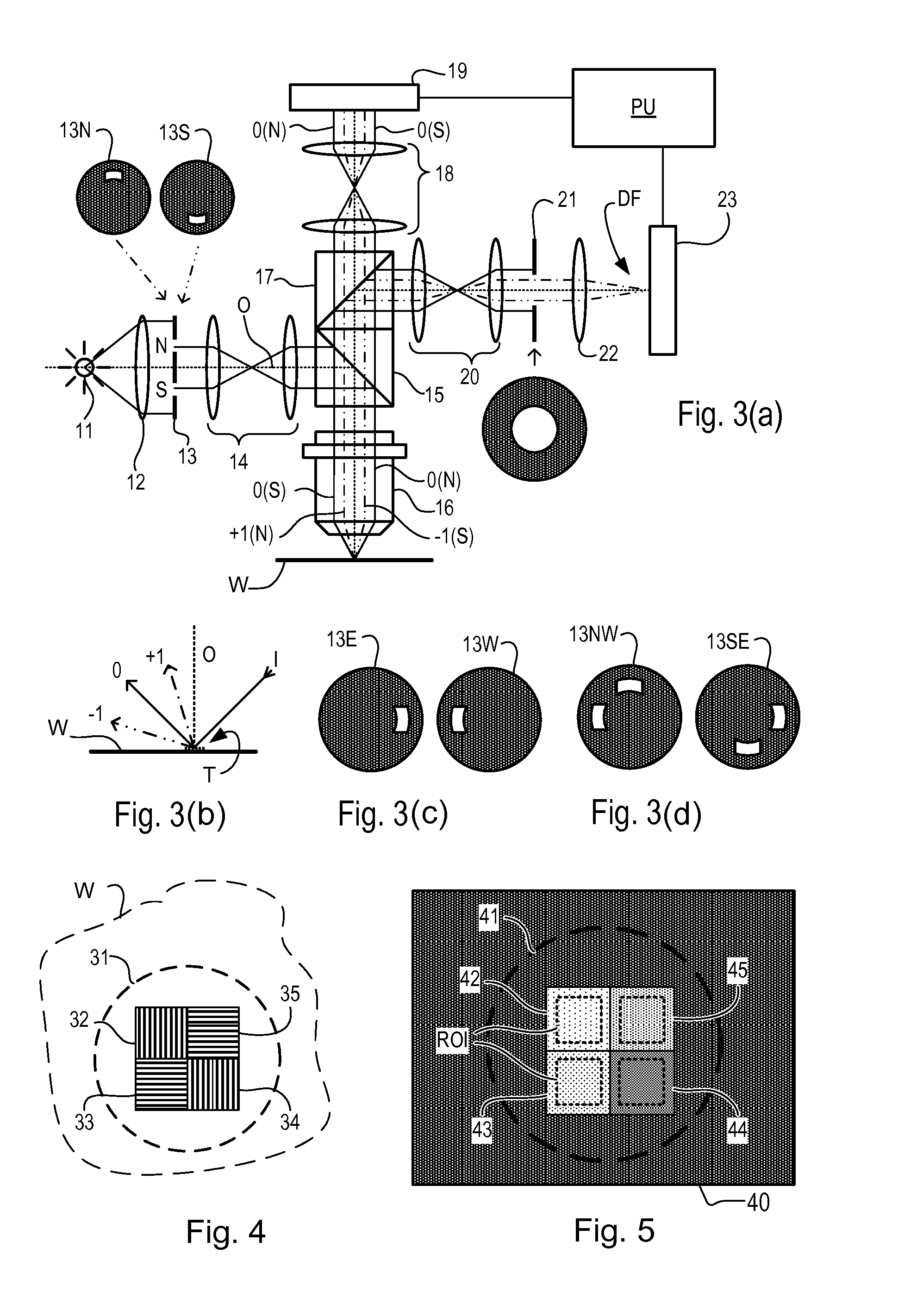
[0119]FIG. 18 illustrates an example target with P=700 nm and a weakened top grating in which ΔCD has been optimized to maximize contrast. A certain bottom grating asymmetry BGA=1 nm has been introduced as an example of a perturbation that is likely to arise in a real manufacturing process. The question for the designer of the metrology target and metrology recipe is how to obtain an accurate measurement of overlay that is relatively robust against such perturbations. It will now be shown how control of the relative phase β is an effective technique to achieve this end. Recall that β can be controlled effectively by selection of the wavelength λ of radiation used in the metrology.

[0120]FIG. 19 shows graphs (a) to (d) of four parameters of the design and measurement method, plotted against a range of wavelengths λ. Graphs (e) and (f) indicate the results. All of these measurements are based on the target of FIG. 18, with its induced bottom grating asymmetry. Measurements can b...


PUM


Abstract

Metrology targets are formed by a lithographic process, each target comprising a bottom grating and a top grating. Overlay performance of the lithographic process can be measured by illuminating each target with radiation and observing asymmetry in diffracted radiation. Parameters of metrology recipe and target design are selected so as to maximize accuracy of measurement of overlay, rather than reproducibility. The method includes calculating at least one of a relative amplitude and a relative phase between (i) a first radiation component representing radiation diffracted by the top grating and (ii) a second radiation component representing radiation diffracted by the bottom grating after traveling through the top grating and intervening layers. The top grating design may be modified to bring the relative amplitude close to unity. The wavelength of illuminating radiation in the metrology recipe can be adjusted to bring the relative phase close to π/2 or 3π/2.

Description

CROSS REFERENCE TO RELATED APPLICATIONS[0001]The present invention is related to U.S. Provisional Patent Application No. 62 / 006,524, which is incorporated by reference herein in its entirety.BACKGROUND[0002]1. Field of the Invention[0003]The present invention relates to methods and apparatus for metrology usable, for example, in the manufacture of devices by lithographic techniques and to methods of manufacturing devices using lithographic techniques.[0004]2. Background Art[0005]A lithographic apparatus is a machine that applies a desired pattern onto a substrate, usually onto a target portion of the substrate. A lithographic apparatus can be used, for example, in the manufacture of integrated circuits (ICs). In that instance, a patterning device, which is alternatively referred to as a mask or a reticle, may be used to generate a circuit pattern to be formed on an individual layer of the IC. This pattern can be transferred onto a target portion (e.g., including part of, one, or sev...

Claims


Application Information

Patent Timeline
IPC IPC(8): G03F7/20G03F9/00H01L23/544
CPCG03F7/705G03F7/70158G03F9/708H01L23/544G03F7/70633G03F7/70683G03F7/70125G03F7/70616
Inventor DEN BOEF, ARIE JEFFREYBHATTACHARYYA, KAUSTUVE
Owner ASML NETHERLANDS BV
Why Eureka
Try Eureka