
Systems and methods for conducting EMI susceptibility testing

a technology of electromagnetic interference and susceptibility testing, which is applied in the direction of noise figure or signal-to-noise ratio measurement, transmission monitoring, instruments, etc., can solve the problems of affecting the effective performance of an electronic device, obstructing, or otherwise, affecting and compromising the normal operation of such systems

Active Publication Date: 2010-11-11
FEDERAL EXPRESS CORP US
View PDF3 Cites 6 Cited by
  • Summary
  • Abstract
  • Description
  • Claims
  • Application Information

AI Technical Summary

Benefits of technology

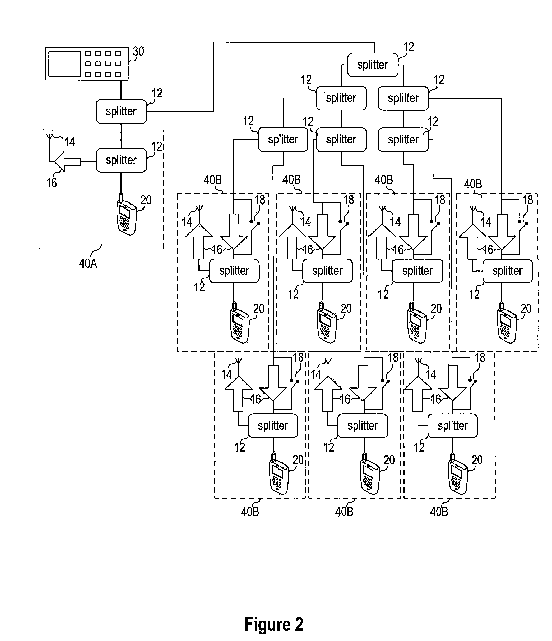
[0009]In some embodiments, each of the cellular handsets in the EMI generation unit may include a SIM card. Each of these SIM cards may contain data that is substantially identical to the others. In some cases, the EMI generation unit may also include a plurality of signal splitters. In some of these cases, each of the plurality of cellular handsets may be electrically coupled to a signal splitter such that a signal emitted by a cellular handset is divided into multiple components. One...

Problems solved by technology

These electromagnetic emissions from one device can interfere with the operation of other devices, causing potential problems.
Additionally, the presence of a radio transmitter within an electronic device dramatically increases emissions that can potentially cause interference, since the intentional emissions created by a radio transmitter are generally several orders of magnitude higher than the emissions produced by a non-transmitting device.
EMI may interrupt, obstruct, or otherwise degrade or limit the effective performance of an affected electronic device.
The increasing use of personal wireless devices, such as cellular phones, in recent years has given rise to several safety concerns due to the risk of electromagnetic interference to electronic components of commercial aircraft.
Depending upon the transmission characteristics of the cellular phone, the cellular phone may create EMI in one of the frequency bands used by aircraft systems, thereby compromising the normal operation of such systems.
However, the frequencies used by cellular phones are restricted and licensed by the FCC to local cellular network operators.
The use of a CW signal generator at high power levels within these frequency bands is equivalent to the use of a cellular “jammer,” and is unlawful in the United States.
Additionally, the EMI signals generated by a CW signal generator do not closely represent the type of EMI produced by a cellular phone.
A CW signal generator may not be able to accurately reproduce this type of EMI.

Method used


Image

  • Systems and methods for conducting EMI susceptibility testing
  • Systems and methods for conducting EMI susceptibility testing
  • Systems and methods for conducting EMI susceptibility testing

Examples


Embodiment Construction

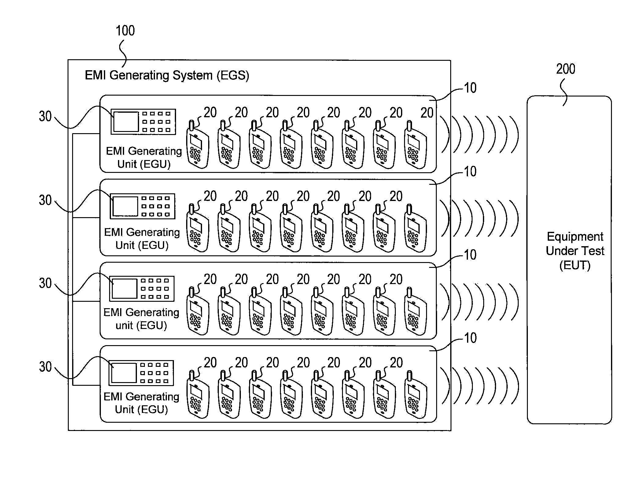
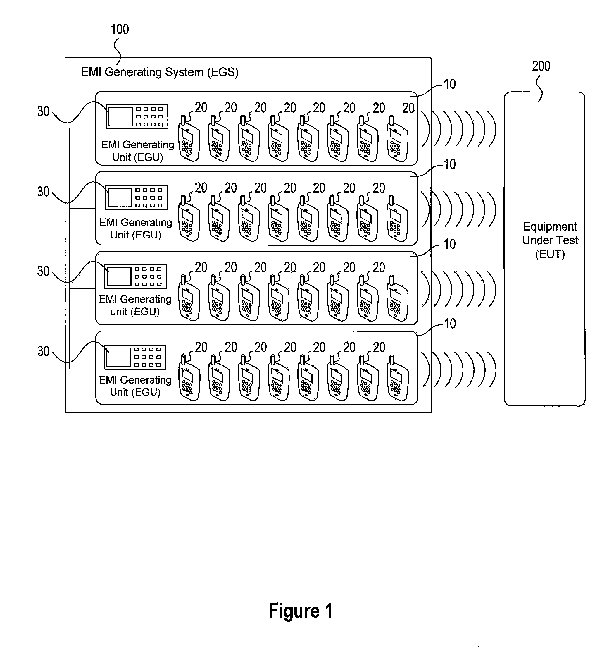
[0018]Embodiments of the current invention include a system and methods for subjecting an electronic system (referred to herein as the equipment under test or EUT) to a high-level of EMI by combining the output from multiple EMI producing devices. In an exemplary embodiment used to describe the invention, these multiple EMI producing devices are cellular phones. However, in general, the EMI producing devices may be any device that produces EMI. An overview of the system design, according one embodiment of the invention, is illustrated in FIG. 1. The system of FIG. 1 is composed of the equipment under test (EUT) 200 subjected to EMI from an EMI generating system 100. The EMI generating system 100 includes a series of EMI generation units (EGU) 10, each of which consists of a bank of eight cellular phones 20 and an EGU control device 30. Although the exemplary EMI generating system 100 shown in FIG. 1 includes four EGUs 10 with eight cellular phones 20 each (representing a total of 32...


PUM


Abstract

System and methods for performing EMI susceptibility testing of a device is disclosed. A system may include an EMI generation unit that includes a plurality of EMI generating devices, where each EMI generating device generates EMI having substantially similar characteristics relative to EMI generated by other EMI generating devices in the system. Each EMI generating device is controlled by a controller that is configured to emulate at least partly a live cellular network.

Description

CROSS RELATED TO RELATED APPLICATIONS[0001]This application is based upon and claims the benefit of priority from U.S. Provisional Application No. 61 / 213,121 to Lemmon filed on May 8, 2009, which is incorporated in its entirety by reference herein.FIELD OF THE INVENTION[0002]This disclosure relates to systems and methods for evaluating the susceptibility of electronic devices to electromagnetic interference (EMI). In particular, this disclosure relates to systems and methods for determining the susceptibility of a device to EMI generated by wireless devices such as, for example, cellular telephones.BACKGROUND OF THE INVENTION[0003]Most electronic devices emit electromagnetic radiation as a by-product of electrical and magnetic activity in the device during operation. These electromagnetic emissions from one device can interfere with the operation of other devices, causing potential problems. This interference in the electrical circuit of one device due to the electromagnetic radiati...

Claims


Application Information

Patent Timeline
IPC IPC(8): G01R29/26
CPCH01Q17/00
Inventor LEMMON, ANDREW N.
Owner FEDERAL EXPRESS CORP US
Learn More