Broadband whip antenna

a whip antenna and antenna technology, applied in the direction of antennas, antenna details, antenna feed intermediates, etc., can solve the problems of affecting the performance of the antenna, the difficulty of fabricating and deploying, and the difficulty of achieving the effect of reducing the size, improving the gain of the uhf dipole, and improving the vswr

Active Publication Date: 2010-11-11
BAE SYST INFORMATION & ELECTRONICS SYST INTERGRATION INC
View PDF8 Cites 35 Cited by
  • Summary
  • Abstract
  • Description
  • Claims
  • Application Information

AI Technical Summary

Benefits of technology

[0019]Moreover, in order to reduce the overall height from 105 inches to 5½ feet, rather than using traditional meander lines, staggered shielded meander lines are utilized to provide better choking or trap functions.
[0029]The above staggered configuration solves this problem by being asymmetric as an intermediate state so that the transition from a full antenna to an abbreviated antenna is more gradual, mitigating the oscillation problem.
[0031]Moreover, it was found that a parasitic re-radiator can be formed at the top of the 225-450 MHz dipole to provide improved gain especially for the upper region of the UHF band.
[0034]Fourthly, staggered shielded meanderlines permit antenna shortening without unwanted oscillations.
[0036]Additionally, the utilization of a base tuning sleeve results in a better VSWR at the low end of 30 megahertz band.
[0041]In summary, a shortened multi-band antenna includes in-line dipoles, selected elements of which having shielded meanderline chokes to be able to switch from an extended dipole at the lower VHF frequencies to a shortened dipole for the UHF band. Additionally, the staggered asymmetric meanderline configuration permits overall size reduction, whereas antenna construction includes an intermediate fiberglass layer over which conductive foil is placed for tuning and for parasitic radiator purposes to improve the gain of the UHF dipole in the upper regions of the band at 450 megahertz. Additionally, at the low end of the 30 megahertz band a sleeve is positioned between the base of the lowest dipole element and ground, with the sleeve provided with two parallel RLC circuits tuned to different bands to improve VSWR at the low end of the VHF band and to eliminate unwanted nulls.

Problems solved by technology

Another problem with this antenna is that it is fabricated utilizing a number of sections of tubing that are screwed together.
It has been found that these antennas are not readily fabricatable and deployable in the field due to the variability when screwing the sections together and due to the fact that from a storage point of view a 105 inch antenna is not practical.
Thus, especially for the Sincgars radio band, providing such an antenna, primarily for voice communications, has its problems.
Moreover, when considering vehicle mounted antennas operating above a ground plane, variability in the ground plane configuration causes matching and radiation pattern problems because vehicle configurations can vary significantly.
While it might be thought that any antenna could be tuned for each vehicle, such antennas are not practical and the simple solution is to simply avoid frequencies where VSWR is high, with the obvious coverage disadvantages.
Moreover, aside from its length and multi-part construction, it was found that standard meander lines used to separate out the bands did not adequately act as traps.
Thus, while various dipoles were designed to operate in various bands, the traps did not function properly to switch from a short to a trap at the band demarcations.
Secondly, especially in the middle and upper bands, the prior antenna did not exhibit sufficient gain so that the antenna could not match or exceed legacy antennas.
Further, it was found that in shortening the prior antenna, linearly downsizing the meander lines did not result in the either sufficient gain or sufficiently low VSWR.
Moreover, it was almost impossible to tune the meander lines once in place.
While these meander lines have been utilized in the past for impedance matching and tuning purposes, they were not utilized to provide chokes or traps between various dipole segments so as to make a single whip operate in a multi-band mode.

Method used


Image

  • Broadband whip antenna
  • Broadband whip antenna
  • Broadband whip antenna

Examples


Embodiment Construction

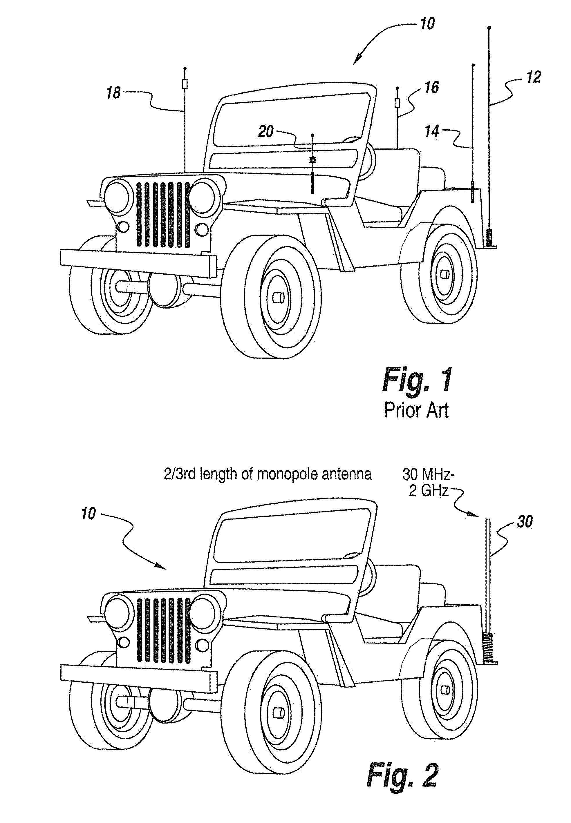
[0057]Referring now to FIG. 1, in the prior art, a vehicle 10 is normally provided with a number of antennas 12-20 tuned to various bands. The fact of having to provide a vehicle with such a large number of antennas for multi-band coverage is problematical and it had been proposed to have an elongated whip, here shown as monopole 12, loaded up to accommodate various bands.

[0058]However, the length of the whip as well as the inefficiencies of providing such a wideband bottom-loaded whip had led to the development of the multi-band antenna described above. This multi-band antenna also had deficiencies which resulted in the development of the subject shortened whip antenna shown in FIG. 2.

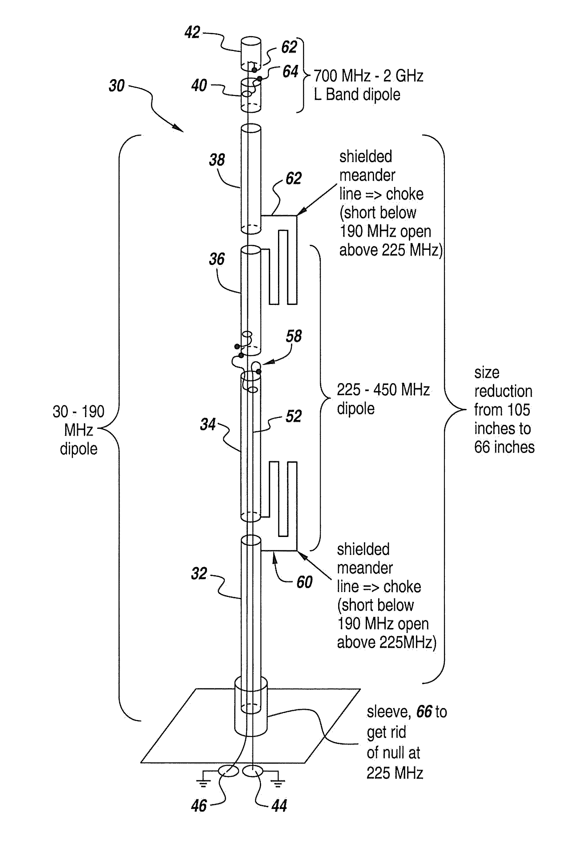
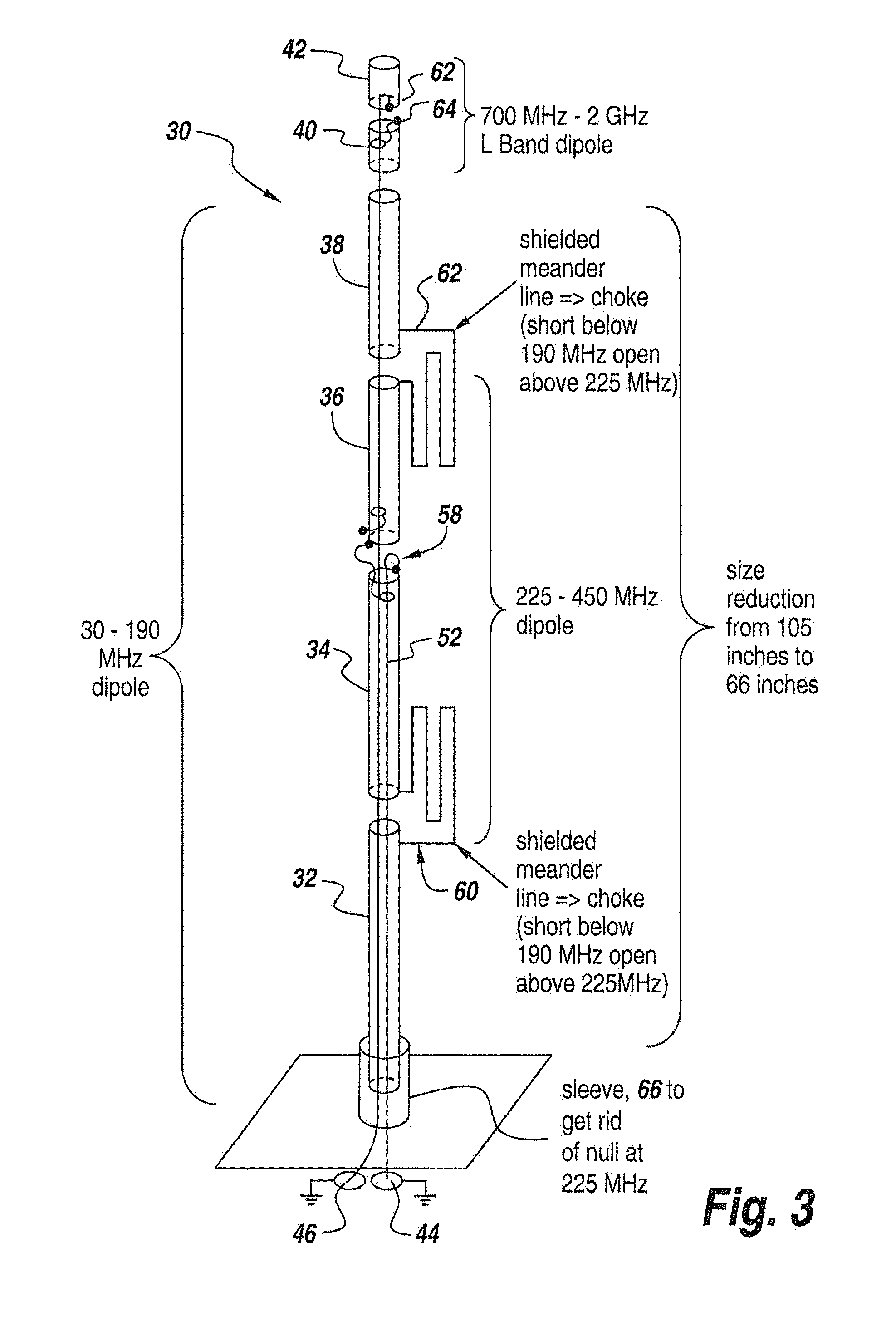
[0059]Here an antenna 30 is mounted to a vehicle 10 in which the overall length of the antenna is ⅔rds of the length of the prior multi-band antenna described in the above patent applications. The coverage of the subject antenna is from 30 megahertz to 2 gigahertz. Note that this antenna is in the for...


PUM


Abstract

A shortened multi-band antenna includes in-line dipoles, selected elements of which having shielded meanderline chokes to be able to switch from an extended dipole at the lower VHF frequencies to a shortened dipole for the UHF band. Additionally, the staggered asymmetric meanderline configuration permits overall size reduction, whereas antenna construction includes an intermediate fiberglass layer over which conductive foil is placed for tuning and for parasitic radiator purposes to improve the gain of the UHF dipole in the upper regions of the band at 450 megahertz. Additionally, at the low end of the 30 megahertz band a sleeve is positioned between the base of the lowest dipole element and ground, with the sleeve provided with two parallel RLC circuits tuned to different bands to improve VSWR at the low end of the VHF band and to eliminate unwanted nulls.

Description

FIELD OF THE INVENTION[0001]This invention relates to broadband communication antennas and more particularly to the utilization of meander line chokes and a vertically stacked series of dipoles to provide for continuous coverage from 30 megahertz up to above 2 gigahertz.BACKGROUND OF THE INVENTION[0002]The military, police and some commercial installations have vehicles that are provided with a virtual forest of antennas to cover various frequency bands. As a result there is a requirement for continuous coverage in a single antenna that operates between from the VHF bands at 30 megahertz all the way up to the 6 UHF gigahertz frequencies.[0003]In order to be able to provide multi-band coverage, up to 4 or 5 antennas are separately utilized on a vehicle. The bands of interest for the military are the 30-88 megahertz band, the 108-156 megahertz band, the 225-450 megahertz band, the 1350-1550 megahertz band and the 1650-1850 megahertz band.[0004]As mentioned above, there is a necessity ...

Claims


Application Information

Patent Timeline
Patent Type & Authority Applications(United States)
IPC IPC(8): H01Q5/00H01Q9/16H01Q5/314H01Q5/378H01Q5/40
CPCH01Q1/3275H01Q9/16H01Q5/40H01Q5/314H01Q5/378H01Q9/32
Inventor APOSTOLOS, JOHN T.FENG, JUDYMOUYOS, WILLIAM
Owner BAE SYST INFORMATION & ELECTRONICS SYST INTERGRATION INC
Why Eureka
Try Eureka