

Gas sensor with an especially explosion-proof housing
- Summary
- Abstract
- Description
- Claims
- Application Information
AI Technical Summary
Benefits of technology
Problems solved by technology
Method used
Image

Examples
Embodiment Construction
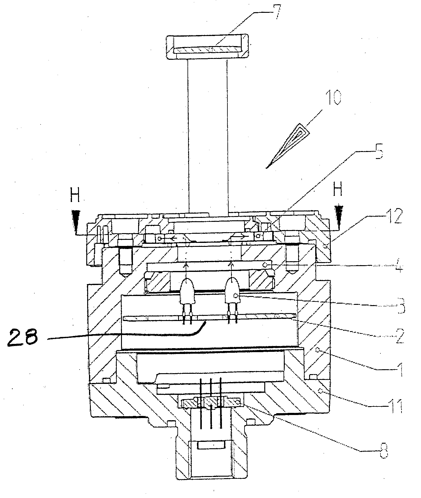
[0023]Referring to the drawings in particular FIG. 1 shows a section through the infrared optical gas sensor 10 with the explosion-proof housing 1, 11 encapsulated in a pressure-proof manner, which is made, for example, of steel.
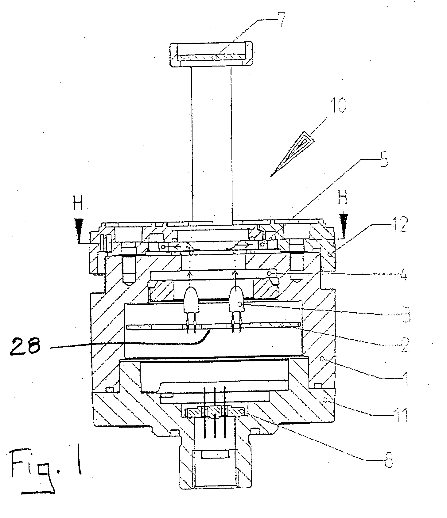
[0024]Two light-emitting diodes (LEDs) 3 are located on a printed circuit board of the measuring module 2 as radiation sources, for example, a yellow LED and a green LED in a 5-mm round housing. The measuring module 2 and LEDs 3 are part of an infrared transceiver. The LEDs have a rather small radiation angle of, e.g., plus / minus 15° and have a luminous density of several candela. The light of the light-emitting diodes 3 is coupled through a disk 4, which is designed as a sapphire disk and is also transparent to infrared light for the measuring beam, into the optical light guide 5, which is beveled at an angle of about 45° and is made of polymethyl methacrylate (PMMA) or polycarbonate (PC). The path of the light to the outer surface 6 of the housing 1, 11 is...
PUM
 Abstract
Description
Claims
Application Information