Stacked optical glass lens array, stacked lens module and manufacturing method thereof

a technology of optical glass and lens array, which is applied in the field of stacked optical glass lens array and stacked lens module, can solve the problems of inability to increase the yield rate, difficult to reduce the cost, and complicated assembling process and precise calibration process

Inactive Publication Date: 2010-11-11
E PIN OPTICAL IND
View PDF13 Cites 29 Cited by
  • Summary
  • Abstract
  • Description
  • Claims
  • Application Information

AI Technical Summary

Benefits of technology

[0020]In accordance with the above method, an optical glass lens array, a stacked optical glass lens array and a stacked lens module are manufactured precisely so as to achieve purposes of precise assembling and mass production.

Problems solved by technology

Thus the assembling requires a complicated processes and precise calibration process.
Therefore, the yield rate is unable to increase and the cost down is difficult.
Since the optical resolution (example as MTF effect) will be affected when the optical assembly having disalignment from optical axis, the lens alignment of the optical lens array is more complicated and important.
However, in the conventional assembling way of projections and holes to form plastic optical lens array, material shrinkage after the plastic injection molding will lead to size change of the projections and the holes.
Thus the location precision is affected and the alignment of the optical axis is difficult.
Therefore, the applications of the plastic optical lens array is limited, especially during manufacturing of small-size lens module, the complicated processes cause cost increase.

Method used


Image

  • Stacked optical glass lens array, stacked lens module and manufacturing method thereof
  • Stacked optical glass lens array, stacked lens module and manufacturing method thereof
  • Stacked optical glass lens array, stacked lens module and manufacturing method thereof

Examples


embodiment one

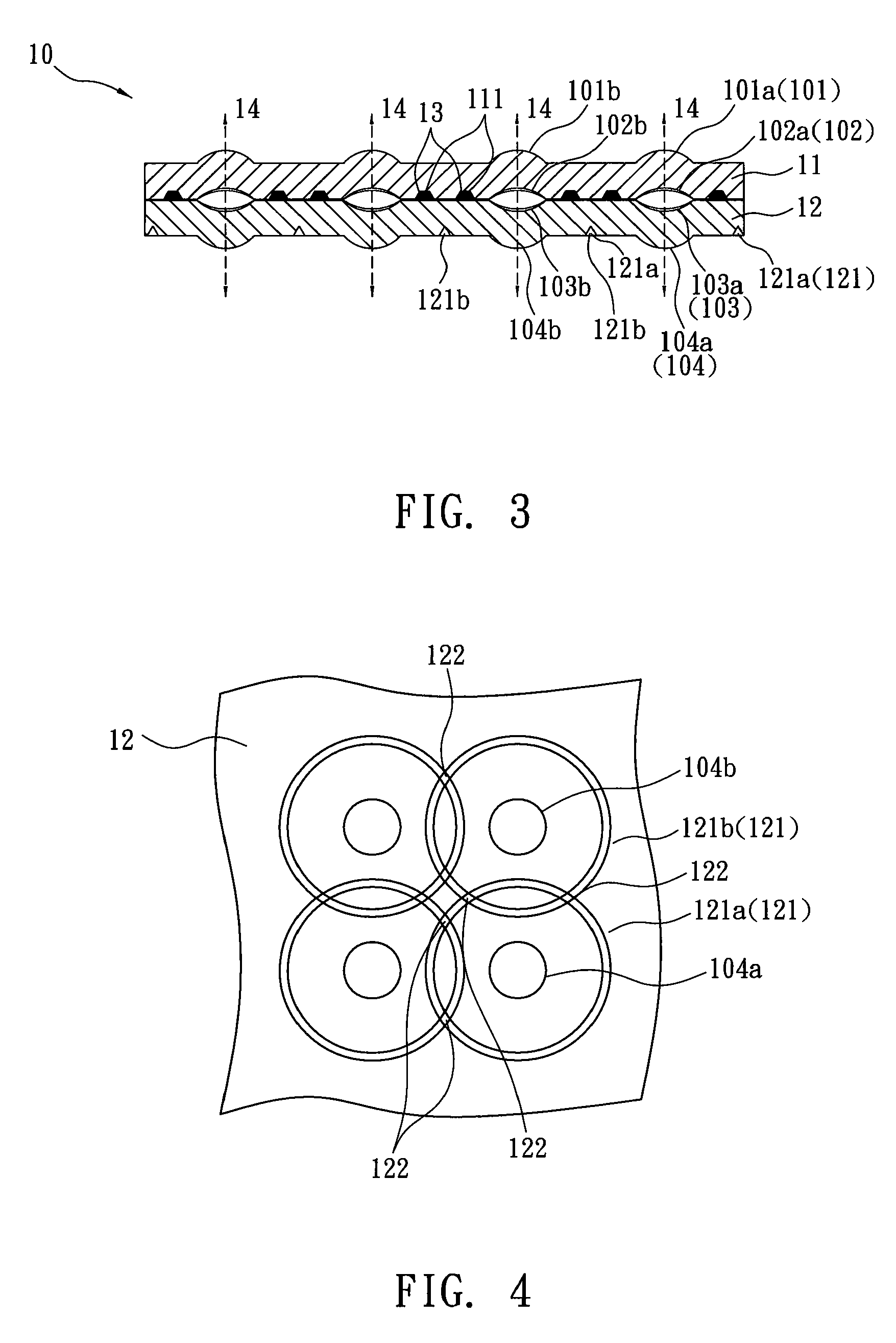
[0039]Refer to FIG. 3, this embodiment is a stacked optical glass lens array that includes a first optical glass lens array 11 and a second optical glass lens array 12, stacked with each other by cement glue 13. The first lens array 11 is disposed with 4×4 first optical surfaces 101 (101a, 101b, . . . ) and 4×4 second optical surfaces 102 (102a, 102b, . . . ). The second optical surface 102 is arranged with 4×4 circular glue grooves 111 whose cross section is a trapezoid. The second lens array 12 is disposed with 4×4 third optical surfaces 103(103a, 103b, . . . ) and 4×4 fourth optical surfaces104(104a, 104b, . . . ).

[0040]While being assembled, the second lens array 12 is mounted into an assembly fixture (not shown in figure). Then each glue groove 111 of the first lens array 11 is filled with the cement glue 13 such as thermoset adhesive and the first lens array 11 is set into the assembly fixture, stacked over the second lens array 12. Thus the first and the second lens arrays 11...

embodiment two

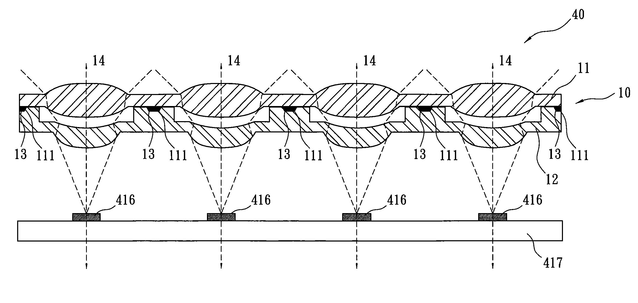
[0041]Refer to FIG. 12, a stacked optical glass lens array in this embodiment is applied to solar energy conversion systems. In order to get excellent solar energy conversion efficiency, a solar transformation module 40 often includes a plurality of optical glass lens arrays so as o make solar light focus on the photoelectric die 416. Thus solar energy is converted into electricity by the photoelectric die 416 and then the electricity is output through a circuit board 417. The solar transformation module 40 consists of a stacked optical glass lens array 10 formed by two optical glass lens arrays 11, 12, a circuit board 417, and a plurality of photoelectric die 416 arranged over the circuit board 417. The stacked optical glass lens array 10, the same as the embodiment one, the first lens array 11 and the second lens array 12 respective include 4×4 corresponding meniscus optical area. In order to make the stacked optical glass lens array 10 have optimal focusing effect, a certain inte...

embodiment three

[0042]Refer to FIG. 10 and FIG. 11, a stacked optical lens element 100 of this embodiment formed by cutting and singularizing of a stacked optical glass lens array 10 is applied to high-precision mobile phone lenses. The stacked optical glass lens array 10 includes a first optical glass lens array 11 and a second optical glass lens array 12, stacked with each other by cement glue 13. The first lens array 11 is disposed with 4×4 first optical surfaces 101 (101a, 101b, . . . ) and corresponding 4×4 second optical surfaces 102 (102a, 102b, . . . ). The second optical surface 102 is arranged with 4×4 glue grooves 111 that is circular and with a trapezoid cross section. The second lens array 12 is disposed with 4×4 third optical surfaces 103(103a, 103b, . . . ) and 4×4 corresponding fourth optical surfaces 104(104a, 104b, . . . ). The fourth optical surface 104 is formed with 4×4 circular V-shaped alignment notches 121(121a, 121b, . . . ) and the center of each alignment notch 121 is on ...


PUM

PropertyMeasurementUnit
distanceaaaaaaaaaa
distanceaaaaaaaaaa
areaaaaaaaaaaa

Abstract

A stacked optical glass lens array, a stacked lens module and a manufacturing method thereof are disclosed. The stacked optical glass lens array includes at least two optical glass lens arrays whose optical axis are aligned and then stacked with each other by cement glue in glue grooves. A stacked optical glass lens element can be singularized by cutting along with the alignment notches of stacked optical glass lens array. The stacked lens module is formed by a single stacked optical glass lens element and related optical element mounted in a lens holder. Thereby the optical axis of the lenses of the stacked lens module are aligned precisely, the manufacturing processes are simplified and the production cost is reduced.

Description

BACKGROUND OF THE INVENTION[0001]The present invention relates to a stacked optical glass lens array, a stacked lens module and a manufacturing method thereof, especially to a stacked lens module formed by a stacked optical glass lens element and other optical elements required mounted in a lens holder. The stacked optical glass lens element is manufactured by cutting a precisely-assembled stacked optical glass lens array. The stacked lens module is applied to assembled lenses of light emitting diode (LED) light sources, assembled lenses of solar energy conversion systems and optical lenses of phone cameras.[0002]Glass precision molding technology has been widely applied to manufacture aspherical molded glass lens with high resolution, good stability and low cost such as lens revealed in US2006 / 0107695, US2007 / 0043463, TW095101830, TW095133807, and JP63-295448 etc. A glass preform (or glass material) is set into a mold having an upper mold and a lower mold to be heated and softening...

Claims


Application Information

Patent Timeline
Patent Type & Authority Applications(United States)
IPC IPC(8): G02B27/12G02B11/02B29D11/00
CPCG02B3/0062G02B3/0075G02B3/0068
Inventor SHYU, SAN-WOEIWU, CHIEN-MINCHEN, HSUEH-LIN
Owner E PIN OPTICAL IND
Why Eureka
Try Eureka