
Dual pump hydraulic system

a hydraulic system and pump technology, applied in the direction of fluid couplings, clutches, servomotors, etc., can solve the problem of excessive power loss

Active Publication Date: 2010-11-18
DEERE & CO
View PDF8 Cites 25 Cited by
  • Summary
  • Abstract
  • Description
  • Claims
  • Application Information

AI Technical Summary

Benefits of technology

[0005]A further object of the invention is to provide such a system which includes an electrically driven pump which may be electronically controlled to vary pump drive speed to provide only the flow desired, resulting in a power savings.
[0006]A further object of the invention is to provide such a system which can, when utilizing electric motor driven pumps, provide adequate pressure and flow at cold oil start up conditions.
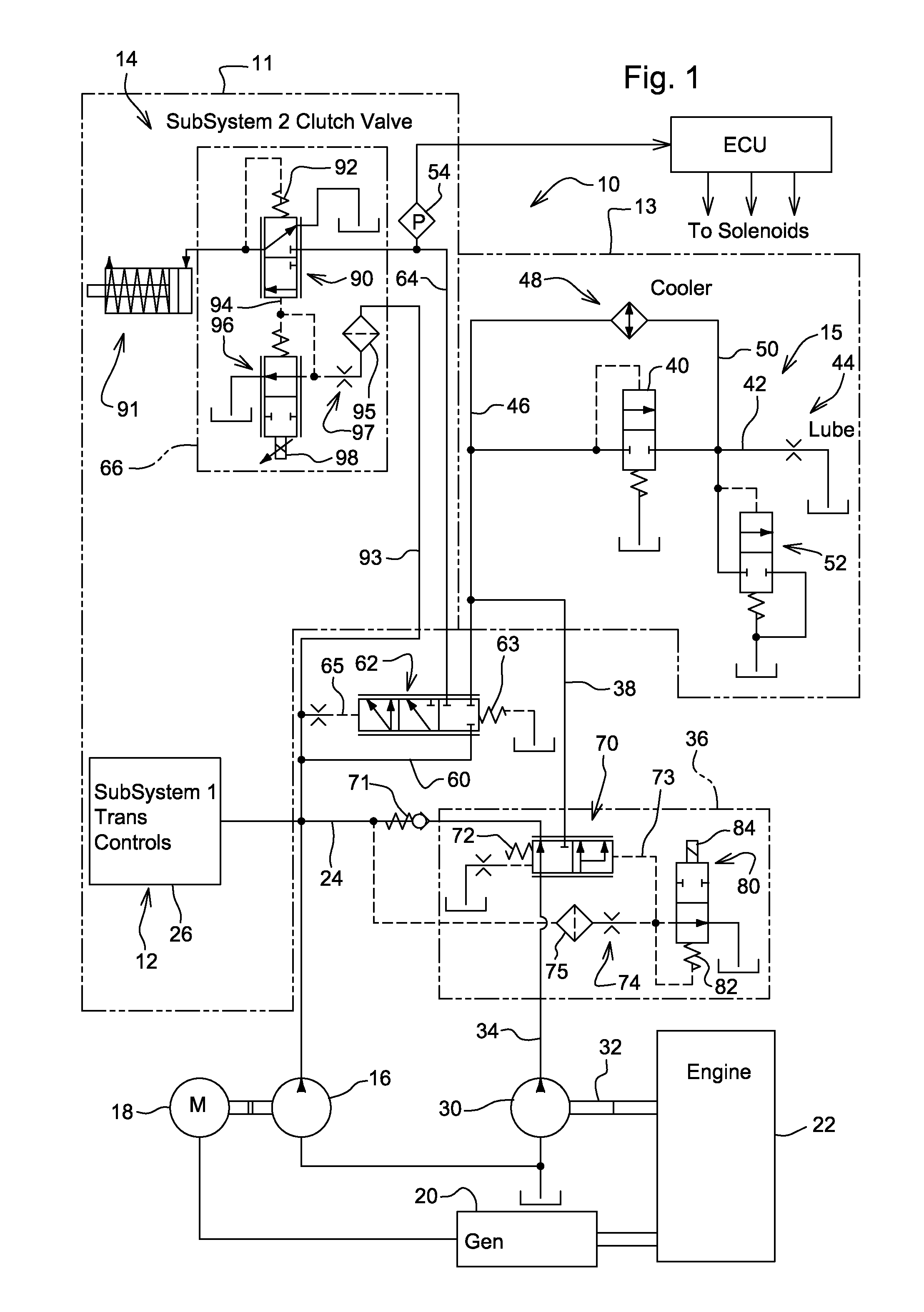
[0008]These and other objects are achieved by the present invention, wherein a hydraulic system is provided for a vehicle driven by an internal combustion engine. The hydraulic system includes a first circuit which has a first pump and a first hydraulic subsystem. The first pump supplies hydraulic fluid to the first subsystem at a first pressure, and is preferably driven by an electric motor. The hydraulic system also includes a second circuit which has a second pump and a second hydraulic subsystem. The second pump supplies hydraulic fluid to the second subsystem at a second pressure, and is preferably mechanically driven. A first valve is operable to communicate the first pump with the second circuit when pressure in the first circuit exceeds a first threshold pressure. A second valve is operable to communicate the second pump with the first circuit when pressure in the first circuit is less than a second threshold pressure. The second valve is connected to the first circuit via a check valve which prevents fluid flow from the first circuit to the second valve.

Problems solved by technology

Thus, excessive power loss is caused by pumping oil at higher flow and higher pressure than necessary to fulfill sub-system requirements.

Method used


Image

  • Dual pump hydraulic system
  • Dual pump hydraulic system
  • Dual pump hydraulic system

Examples


Embodiment Construction

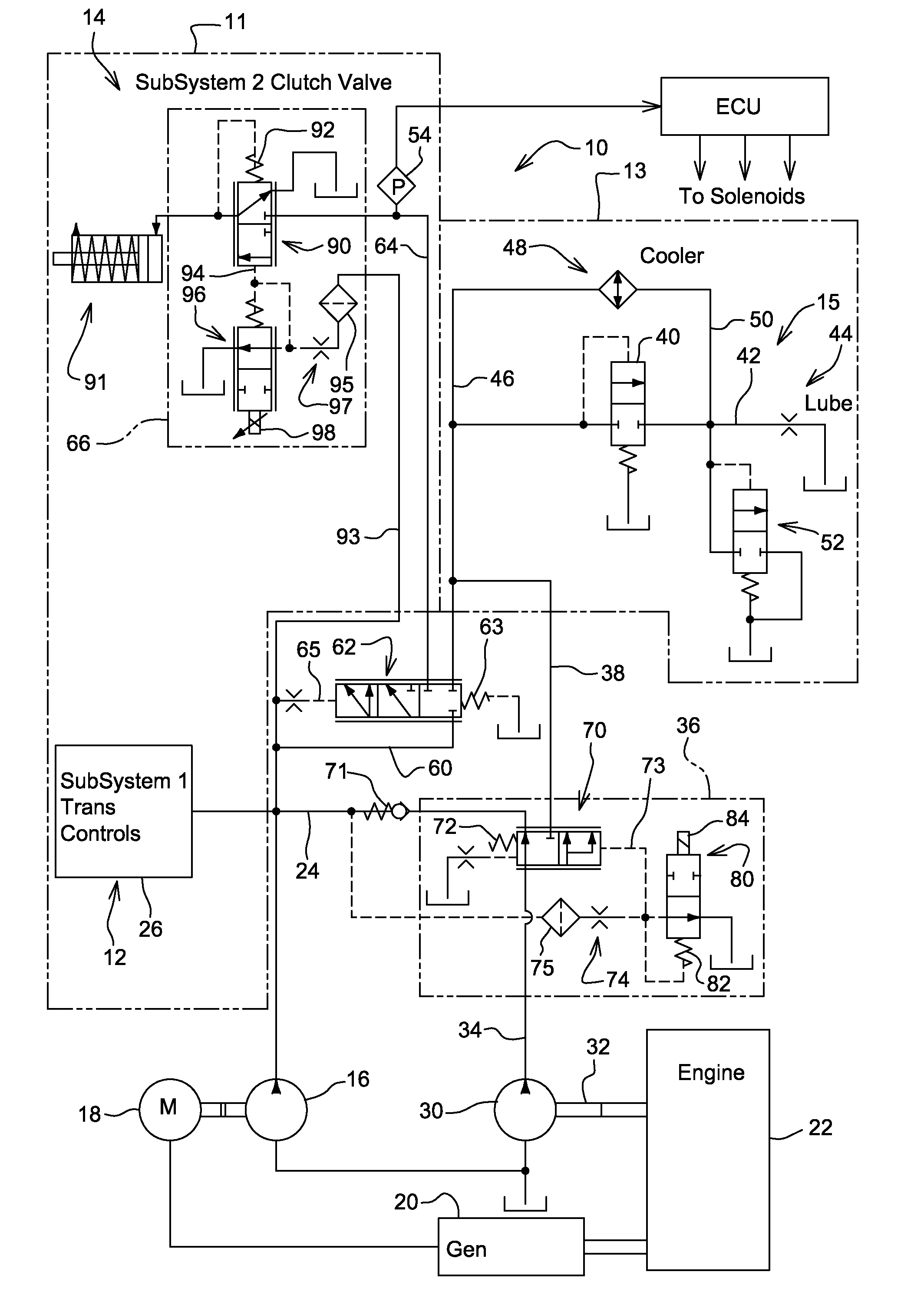
[0011]Referring to FIG. 1, the dual pump hydraulic system 10 includes a first circuit or system 11 and a second circuit or system 13. First system 11 includes a transmission control hydraulic circuit 12 and a clutch control circuit 14. The second system 13 includes a transmission lube and cooling circuit 15. The transmission control circuit 12 includes a higher pressure transmission control pump 16 which may be driven by an electric motor 18 which is preferably powered by a generator or alternator 20 driven by the engine 22. Line 24 communicates pump 16 to the transmission controls 26. Pump 16 may be driven by electric motor 18 or it may be driven mechanically by the engine, such as by a belt or shaft drive (not shown). The transmission controls 26 may be the controls for a powershift transmission (not shown) or for the hydrostatic pump or motor of a infinitely variable transmission (IVT) (not shown).

[0012]A lube and cooling lower pressure pump 30 may be driven mechanically by the e...


PUM


Abstract

A dual pump hydraulic system is provided for a vehicle driven by an internal combustion engine. The system includes a first circuit with a first high pressure pump supplying hydraulic fluid to the first subsystem at a higher pressure. The system also includes a second circuit with a second lower pressure pump supplying hydraulic fluid to the second subsystem at a second pressure. A first valve controls communication between the first pump and the second circuit. A second valve is operable to communicate the second pump with the first circuit when pressure in the first circuit is less than a second threshold pressure or when commanded by a control unit. A check valve prevents fluid flow from the first circuit back into to the second valve.

Description

FIELD OF THE INVENTION[0001]The present invention relates to a dual pump hydraulic system for a vehicle, such as for a vehicle having a transmission hydraulic control, cooling, and lubrication system.BACKGROUND OF THE INVENTION[0002]Current production hydraulically controlled transmission systems normally include a single hydraulic pump driven mechanically by the engine. This single pump provides hydraulic fluid to all fluid consuming subsystems, such as the hydraulic transmission control valve circuit and the transmission lubrication circuit. This single pump will deliver hydraulic fluid at the highest pressure required by any one of the subsystems. This pressure may exceed the pressure required for some of the subsystems. Thus, excessive power loss is caused by pumping oil at higher flow and higher pressure than necessary to fulfill sub-system requirements. The mechanically driven transmission pump provides a flow rate proportional to engine speed, rather than the flow required by...

Claims


Application Information

Patent Timeline
Patent Type & Authority Applications(United States)
IPC IPC(8): B60T8/48F16D31/02
CPCF15B11/17F15B2211/20515F15B2211/20523F15B2211/20592F15B2211/30505F15B2211/6309F15B2211/41563F15B2211/41572F15B2211/428F15B2211/62F15B2211/4053
Inventor DOSTAL, GARY L.WALLESTAD, STEVEN D.JEFFRIES, DENNIS L.LINDSAY, RYAN
Owner DEERE & CO
Learn More