Track for Patient Lift Devices

Inactive Publication Date: 2010-11-18
PRISM MEDICAL
View PDF16 Cites 11 Cited by
  • Summary
  • Abstract
  • Description
  • Claims
  • Application Information

AI Technical Summary

Benefits of technology

[0007]Therefore, what is desired in one aspect of the invention is a curved track section that is shorter than existing curved track sections, and that can fit into smaller spaces. Such shorter sections would reduce or eliminate the need for expensive turntables and the like to deal with small spaces, and would increase the flexibility of the curved section to allow it to be employed more productively. In addition, a shorter curve would require fewer fixing brackets, making it cheaper and easier to use.
[0008]In another aspect of the invention, what is desired is a curved track section that can be effectively fixed to the ceiling without long straight portions, and without necessarily having a gradual curve.

Problems solved by technology

However, often, such patients may be too heavy to lift, or the attendant may not have enough strength to help the patient move.
Getting up, going to the bathroom, or having a bath, are examples of activities that can be very difficult for such patients.
When the track is curved, the fixing features on the track are curved, and they don't fit as well with the fixing features on the brackets.
Ineffective fixation can lead to the track coming away from the ceiling, creating a large risk of serious injury to the patient.

Method used


Image

  • Track for Patient Lift Devices
  • Track for Patient Lift Devices
  • Track for Patient Lift Devices

Examples


Embodiment Construction

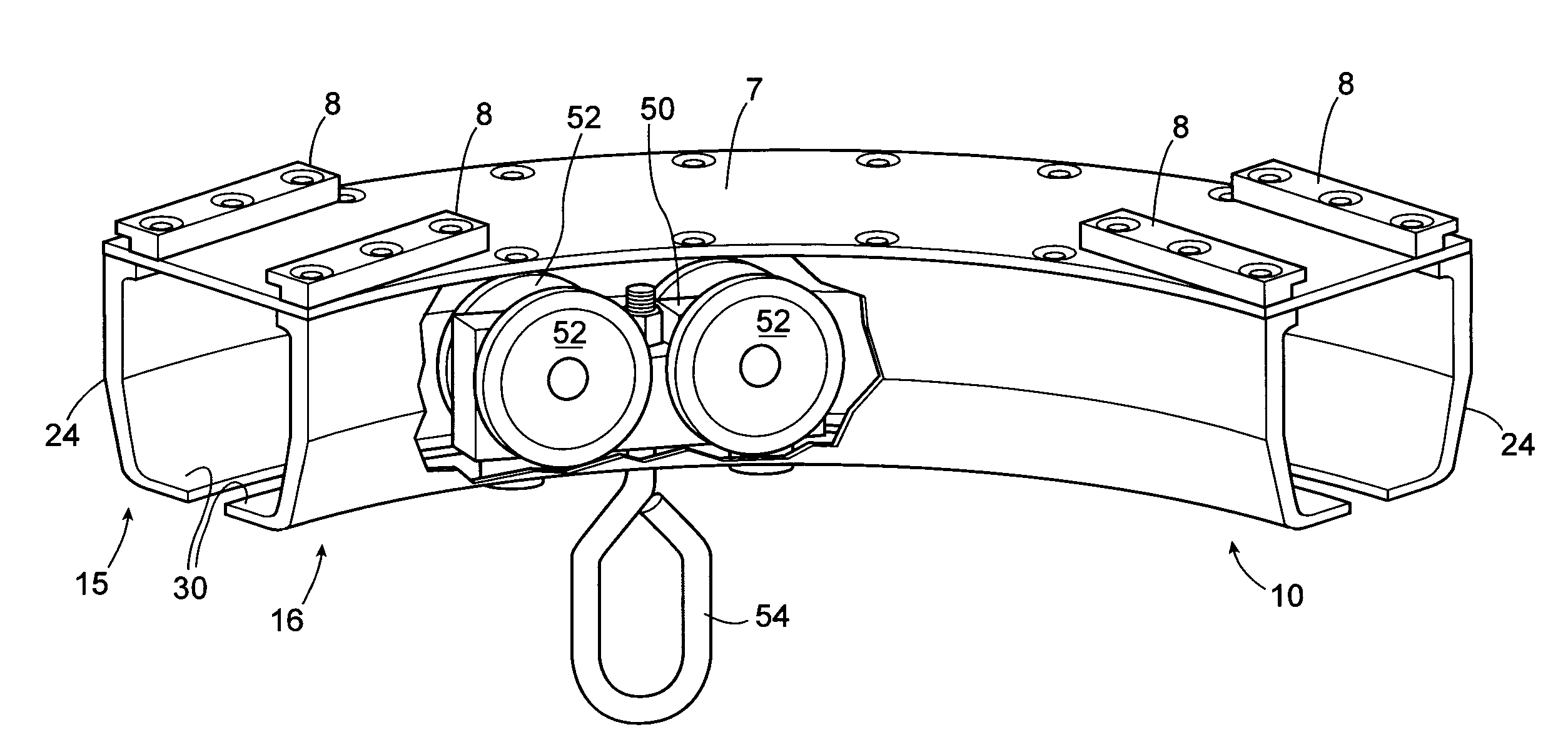
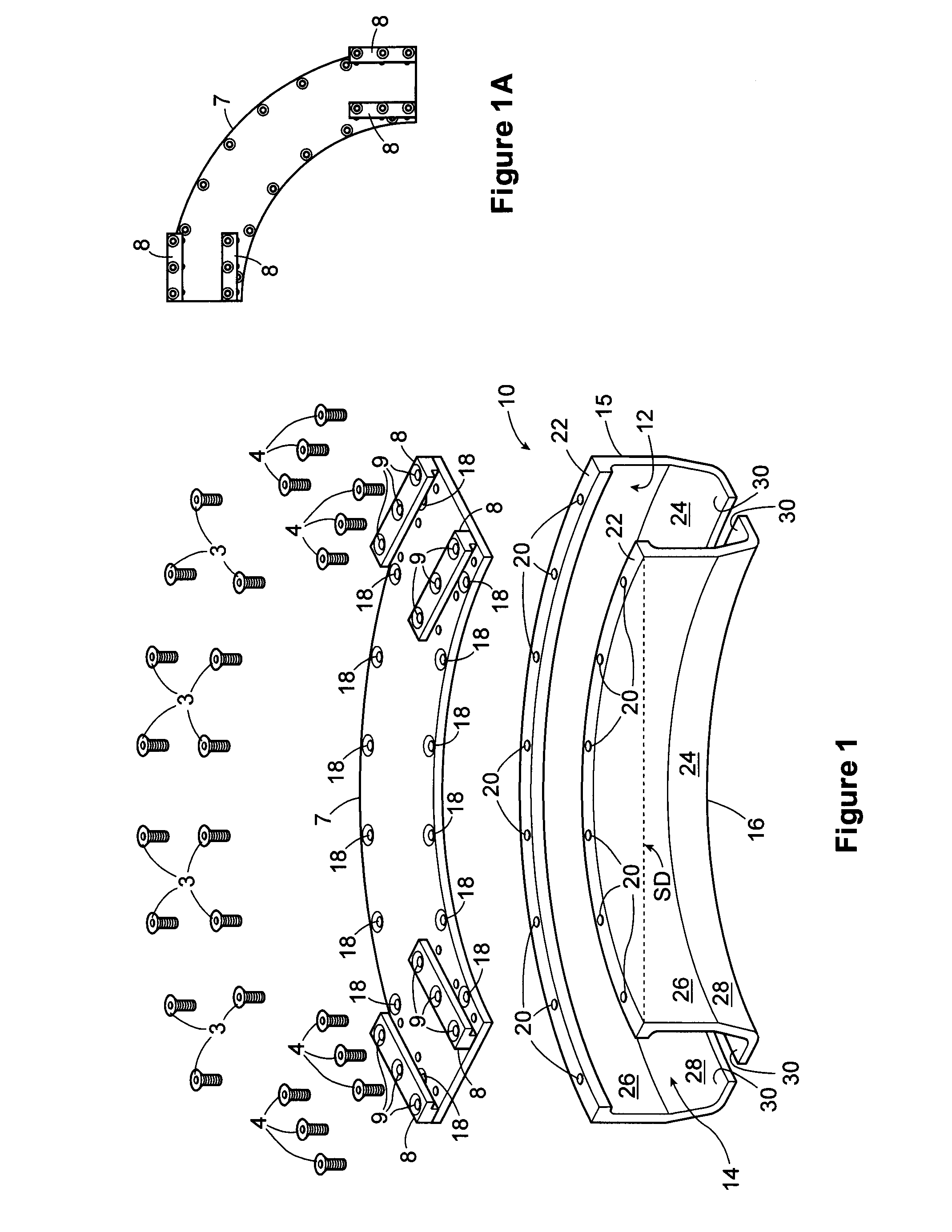
[0028]Referring now to FIGS. 1-9, an exploded view of preferred track section 10 is shown. The preferred track section comprises a connecting piece 7 and two carriage-supporting pieces 15 and 16. The track section is preferably a curved track section that traverses an angle of about 90 degrees. Thus, the direction D1 in which a carriage 50 (see FIGS. 8-9) is travelling when it enters or leaves end 12 of section 10 is angled at about 90 degrees to the direction D2 that a carriage is travelling when it enters or leaves the other end 14 of the section 10. In this specification, a track section comprises a length of track that can be connected to or disconnect from adjacent lengths of track.

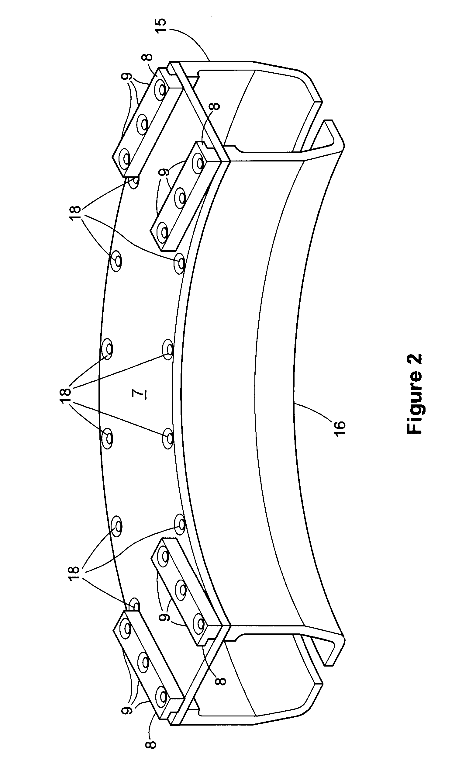
[0029]FIG. 2 shows the section 10 in assembled form. Connecting piece 7 is fixed to carriage-supporting pieces 15 and 16 by at least one fixer, preferably comprising screws 3 that are screwed through connecting piece screw holes 18 and carriage supporting pieces screw holes 20 (see FIG. 1). Holes 18 ...


PUM

PropertyMeasurementUnit
Angleaaaaaaaaaa
Distanceaaaaaaaaaa
Distanceaaaaaaaaaa

Abstract

A track section for use with a patient carrying device, the device having a carriage, and the track section being configured such that the carriage can move along the track to carry a patient, the track section comprising a connecting piece, first and second carriage-supporting pieces, and at least one fixer fixing said connector piece to said first and second carriage-supporting pieces, the track section being shaped to traverse an angle of about 90 degrees.

Description

FIELD OF THE INVENTION[0001]This invention relates generally to the field of mobility devices, and more particularly, to personal lift devices of the type that may be used to raise, lower or transport horizontally a physically disabled patient for the purpose of moving the patient.BACKGROUND OF THE INVENTION[0002]Personal lift or patient lift devices have been known and used in the past for the purpose of assisting with the mobility of otherwise immobilized patients. An attendant may help physically disabled patients who may be elderly, or who may have suffered a traumatic injury, stroke, or one form of illness or another, and who are unable to move about on their own.However, often, such patients may be too heavy to lift, or the attendant may not have enough strength to help the patient move. This can be especially true for disabled patients who have reduced mobility, but otherwise normal bodily functions. Getting up, going to the bathroom, or having a bath, are examples of activit...

Claims


Application Information

Patent Timeline
IPC IPC(8): B61B3/00B23P15/00
CPCY10T29/49963A61G7/1042B66C7/02B66C7/12B23P15/00
Inventor CHEPURNY, MARKHASHEMI, VAHIDEH
Owner PRISM MEDICAL
Why Eureka
Try Eureka