
Process to manufacture magnetic tunnel junction read head

a technology of magnetic tunnel junction and read head, which is applied in the field of magnetic tunnel junction read head, can solve the problems of not disclosing any particular advantage of xenon and limiting its effectiveness to some extent, and achieve the effect of improving design tolerance and increasing cos

Inactive Publication Date: 2008-02-14
HEADWAY TECH INC +1
View PDF9 Cites 0 Cited by
  • Summary
  • Abstract
  • Description
  • Claims
  • Application Information

AI Technical Summary

Benefits of technology

[0017] These objects have been achieved by using xenon ions to perform the ion milling step needed to form the main pedestal. Using xenon enables the vertical section of the pedestal to be made longer, relative to the sloping portion, without requiring an increase in the sputtering rate. This allows the point at which milling is terminated to be controlled more precisely and, thus, also improves design tolerances. In this way it can be ensured that the free layer always has truly vertical sidewalls so the bias magnets cannot overlap it (CIP case) and (for all head types) the read width becomes more precisely defined. These benefits that arise from the use of xenon outweigh its significantly greater cost relative to both argon and krypton.

Problems solved by technology

As can be seen, because of the taper in the stack profile, the thickness of the bias layer is somewhat greater at the bottom of the free layer than at its top, so the bias layer partly overlies the free layer, thereby limiting its effectiveness to some extent.
In U.S. Pat. No. 6,554,974, Shiratori confirms that any of several heavy ions, including Xe ions, may be used for sputter etching but does not disclose any particular advantage of xenon over the others.

Method used


Image

  • Process to manufacture magnetic tunnel junction read head
  • Process to manufacture magnetic tunnel junction read head
  • Process to manufacture magnetic tunnel junction read head

Examples


Embodiment Construction

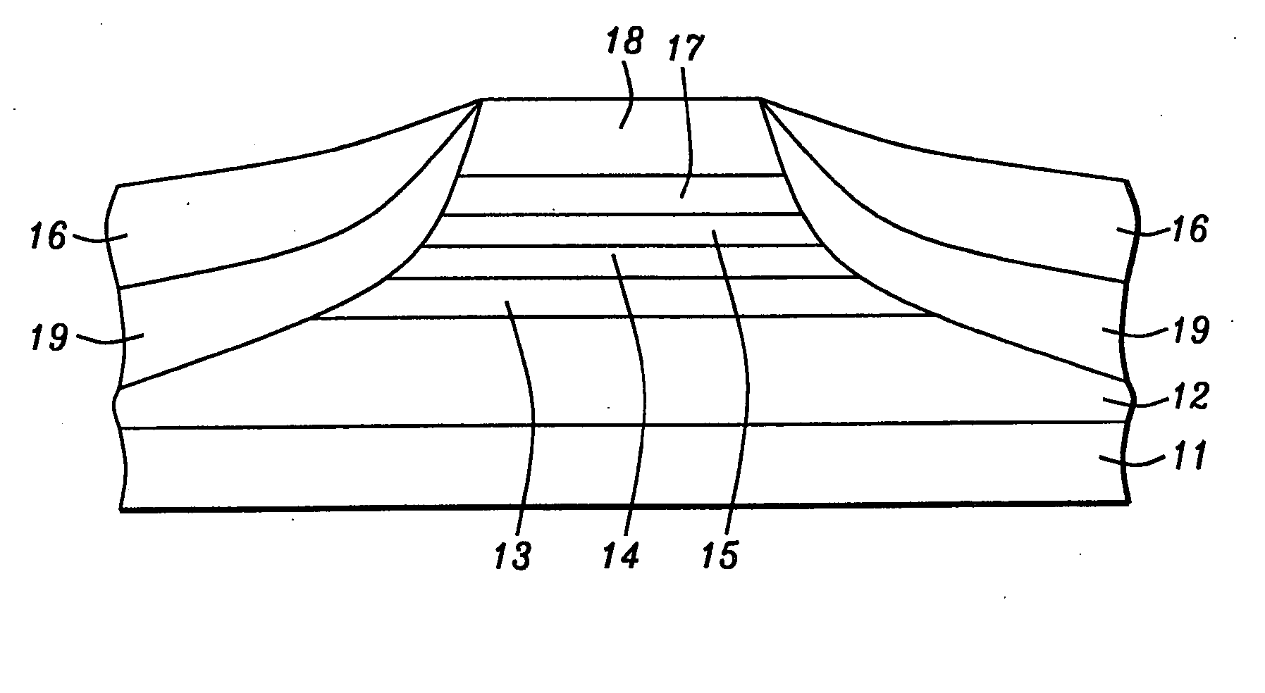
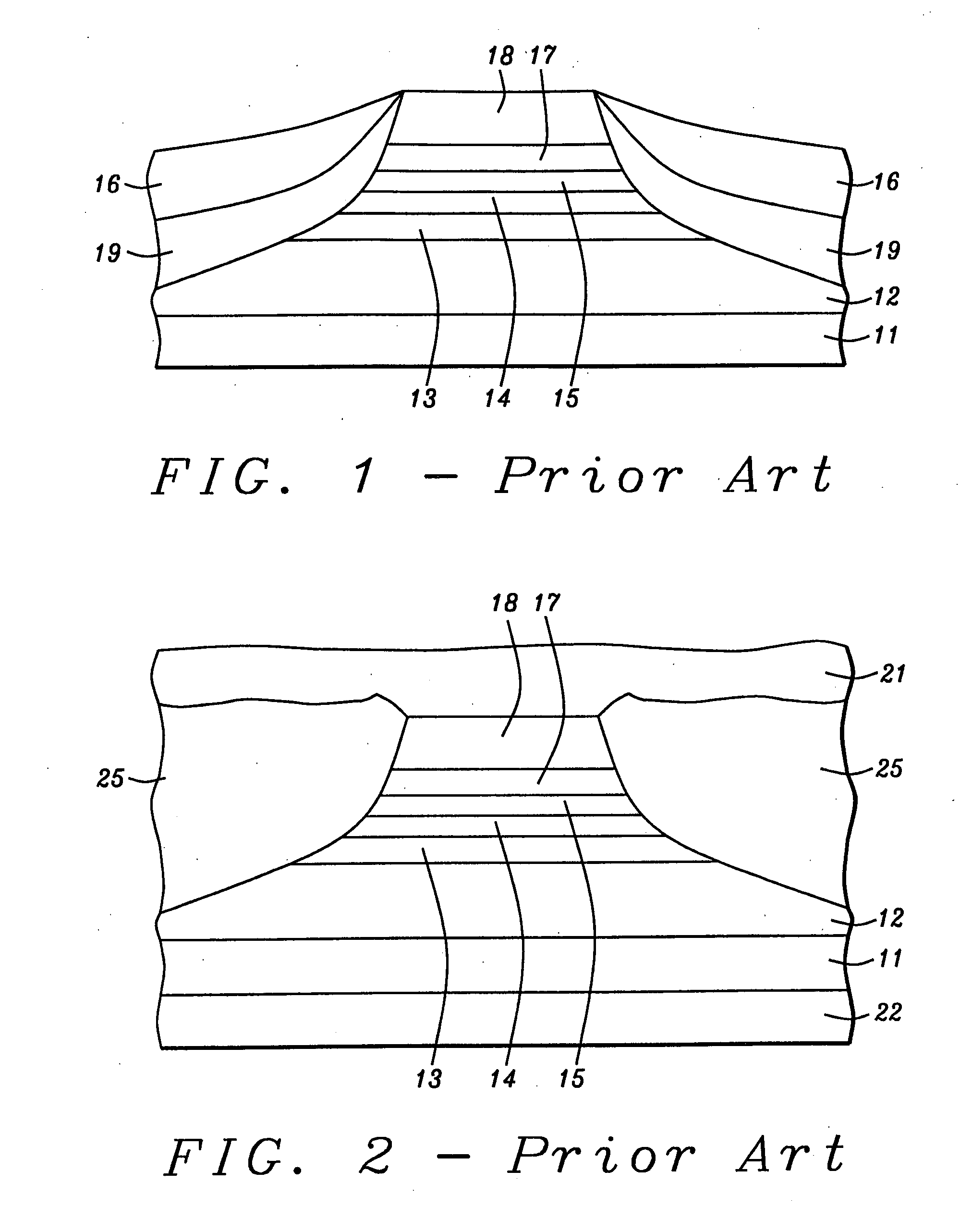
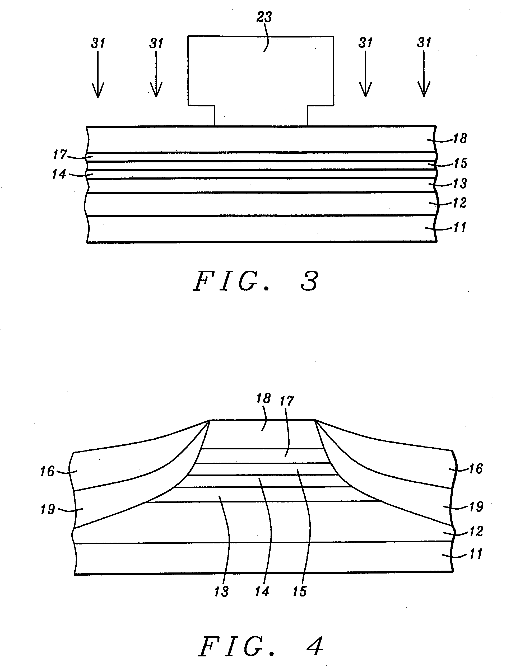
[0022] During the fabrication of CPP magnetic recording heads, an ion beam etch (IBE) is normally used, as illustrated in FIG. 3. A critical aspect of this sub-process is the CPP track width definition. It is critical because the precision of the etch stop point and the sidewall profile directly define device geometry (and hence impact device performance). Typically, the IBE process consists of the following steps: [0023] 1. Bottom conductor 21 and the GMR stack (or, in this case, MTJ stack) are deposited prior to the CPP track width definition process. [0024] 2. Mask 23 is formed to define the nominal CPP track width, as shown in FIG. 3. This mask can be a single or multi-layered photoresist, the latter being selected if a liftoff process is to be used. Hard masking materials such as Ta, SiO2 etc. could also be used for the mask. [0025] 3. Ion beam 31 is used to remove MTJ materials from areas not protected by the mask, as shown in FIG. 2. Ar gas is typically used to generate the p...


PUM

PropertyMeasurementUnit
angle of incidenceaaaaaaaaaa
current densityaaaaaaaaaa

Abstract

Using a beam of xenon ions together with a suitable mask, a MTJ stack is ion milled until a part of it, no more than about 0.1 microns thick, has been removed so that a pedestal, having sidewalls comprising a vertical section that includes all of the free layer, has been formed. This is followed by formation of the longitudinal bias and conductive lead layers in the usual way. Using xenon as the sputtering gas enables the point at which milling is terminated to be more precisely controlled.

Description

[0001] This is a divisional application of U.S. patent application Ser. No. 10 / 827,950, filed on Apr. 20, 2004, which is herein incorporated by reference in its entirety, and assigned to a common assignee.FIELD OF THE INVENTION [0002] The invention relates to the general field of magnetic read heads with particular reference to formation of the main pedestal through ion milling. BACKGROUND OF THE INVENTION [0003] The principle governing the operation of most magnetic read heads is the change of resistivity of certain materials in the presence of a magnetic field (magneto-resistance or MR). Magneto-resistance can be significantly increased by means of a structure known as a spin valve where the resistance increase (known as Giant Magneto-Resistance or GMR) derives from the fact that electrons in a magnetized solid are subject to significantly less scattering by the lattice when their own magnetization vectors (due to spin) are parallel (as opposed to anti-parallel) to the direction o...

Claims


Application Information

Patent Timeline
Patent Type & Authority Applications(United States)
IPC IPC(8): G11B5/127G01R33/09G11B5/33G11B5/39H01F10/32H01F41/30
CPCB82Y10/00Y10T29/49021B82Y40/00G01R33/093G01R33/098G11B2005/3996H01F10/3263H01F41/308Y10T29/49046Y10T29/49044Y10T29/49041Y10T29/49048Y10T29/49039Y10T29/49052Y10T29/49037Y10T29/49043B82Y25/00
Inventor KAO, STUARTLUO, CHUNPINGCHEN, CHAOPENGMACHITA, TAKAHIKOMIYAUCHI, DAISUKECHANG, JEIWEI
Owner HEADWAY TECH INC
Learn More