
Two-sectioned back-pressured catalytic converter

a back-pressured, catalytic converter technology, applied in the direction of engines, mechanical equipment, machines/engines, etc., to achieve the effect of reducing the pressure and temperature of the carrier and improving the discharge efficiency

Inactive Publication Date: 2019-05-23
JUMBOMAW TECH
View PDF5 Cites 0 Cited by
  • Summary
  • Abstract
  • Description
  • Claims
  • Application Information

AI Technical Summary

Benefits of technology

The present invention is a two-sectioned back-pressured catalytic converter that reduces pressure and temperature of the carrier to prevent damage to turbine blades and improves discharge efficiency. The honeycomb carrier has different densities in two sections with higher density in the first section to provide space for expansion and reduce back pressure. A baffle formed by the tail tube creates turbulence and allows toxic gas to stay in the second section longer for full conversion.

Problems solved by technology

In addition, the baffle formed by the tail tube which is mounted into the main body creates turbulence when the toxic gas passing through the second section so that the toxic gas can stay in the second section longer to be fully converted.

Method used


Image

  • Two-sectioned back-pressured catalytic converter
  • Two-sectioned back-pressured catalytic converter
  • Two-sectioned back-pressured catalytic converter

Examples


Embodiment Construction

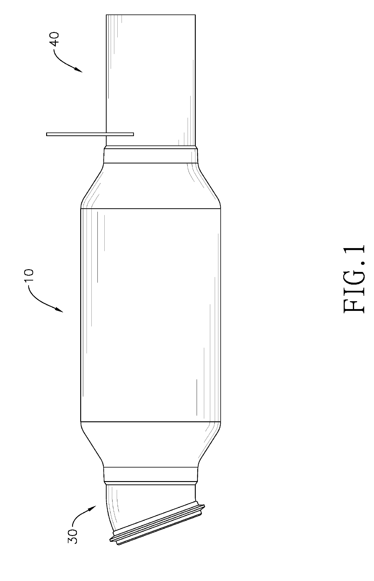
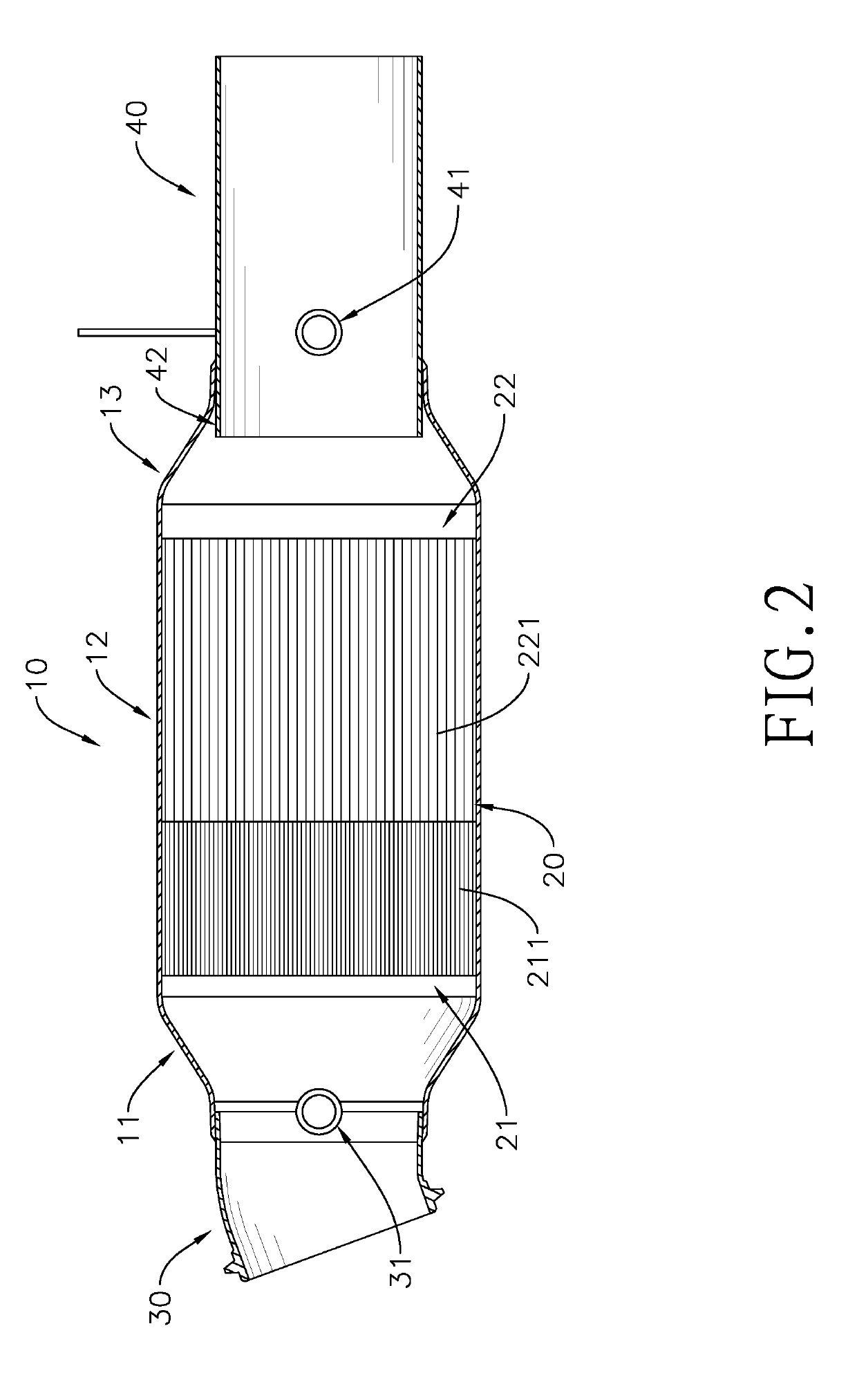
[0017]With reference to FIGS. 1 and 2, a two-sectioned back-pressured catalytic converter in accordance with the present invention comprises a main body 10, a honeycomb carrier 20, a connecting tube 30, and a tail tube 40.

[0018]The main body 10 is hollow and has an intake opening and an exhaust opening. In a preferred embodiment, the main body 10 further comprises an expanding section 11, a carrier section 12, and a tapered section 13 which are sequentially connected to one another. An opening of the expanding section 11 is said intake opening, and an inner diameter of the expanding section 11 progressively increases from the intake opening to the carrier section 12. An opening of the tapered section 13 is said exhaust opening, and an inner diameter of the tapered section 13 progressively decreases from the carrier section 12 to the exhaust opening. But an inner diameter of the main body 10 is not limited to the above mentioned, as the main body 10 can be implemented without the exp...


PUM


Abstract

A two-sectioned back-pressured catalytic converter has a main body, a tail tube, and a honeycomb carrier. The honeycomb carrier is mounted securely in the main body and has a first section relatively proximal to the intake opening and a second section relatively proximal to the exhaust opening. The density of the holes of the first section is higher than that of the second section. Therefore, waste gas has sufficient space for expansion when passing through the first section, and thus the pressure and the temperature are both lowered, solving problems of the back pressure and the backward pushing. The tail tube is securely mounted into the main body to form a baffle. The waste gas will hit the baffle after passing the honeycomb carrier and generate turbulence which can slow down the gas and make the gas fully react with the precious metal coating.

Description

BACKGROUND OF THE INVENTION1. Field of the Invention[0001]The present invention relates to a catalytic converter of an exhaust pipe of an internal combustion engine, especially to a catalytic converter for vehicles.2. Description of the Prior Arts[0002]A catalytic converter is a device mounted in an exhaust pipe, adopts precious metal coating such as Platinum, Palladium, and Rhodium as catalyst, and reduces the toxic gas by catalytic mechanism. In order to fully convert the toxic gas, the prior arts generally use a honeycomb carrier to increase the surface area to complete the reaction.[0003]Conventionally, a catalytic converter is combined with a main body and the honeycomb carrier. The main body is a hollow tube that may be in any shape, and the honeycomb carrier is mounted in the main body. The section of the honeycomb carrier is a high-density grid structure, and the aforementioned precious metal coating is deposited on the walls of the holes of the honeycomb carrier.[0004]A den...

Claims


Application Information

Patent Timeline
IPC IPC(8): F01N3/28F01N13/08
CPCF01N3/2842F01N13/08F01N2330/48F01N2370/02F01N2470/20F01N3/2807F01N13/082F01N2240/36F01N2330/60
Inventor CHANG, HSIN-CHANG
Owner JUMBOMAW TECH
Learn More