
Illumination device

a technology of illumination device and gradation, which is applied in the direction of static indicating device, electroluminescent light source, instruments, etc., can solve the problems of difficult enlargement of gradation, high cost of component configuration, and flickering of picked-up pictures, so as to reduce flickering occurrence, low lighting, and easy brightness change

Inactive Publication Date: 2010-11-18
TOSHIBA LIGHTING & TECH CORP +1
View PDF83 Cites 24 Cited by
  • Summary
  • Abstract
  • Description
  • Claims
  • Application Information

AI Technical Summary

Benefits of technology

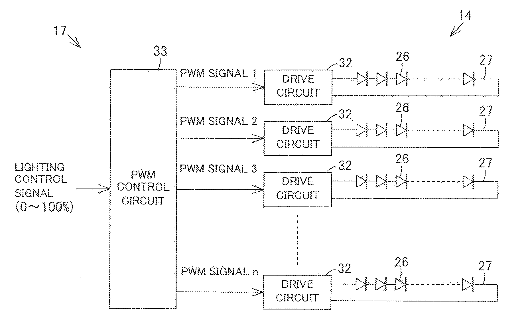
[0010]Thus, since, by making the output timings of the PWM signals output from the PWM control circuit different from each other per drive circuit, the period of time during which the LEDs are turned off can be reduced as the entirety of the light source portion even if the lighting control ratio is lowered, a change in the brightness is reduced, and it is possible to reduce the occurrence of flickering without increasing the lighting frequency. Therefore, since it is not necessary to increase the lighting frequency to reduce flickering, the component configuration can be made inexpensive by lowering the lighting frequency. In addition, since the lighting frequency is not high, the LEDs can be smoothly controlled for lighting by enlarging the number of gradations.
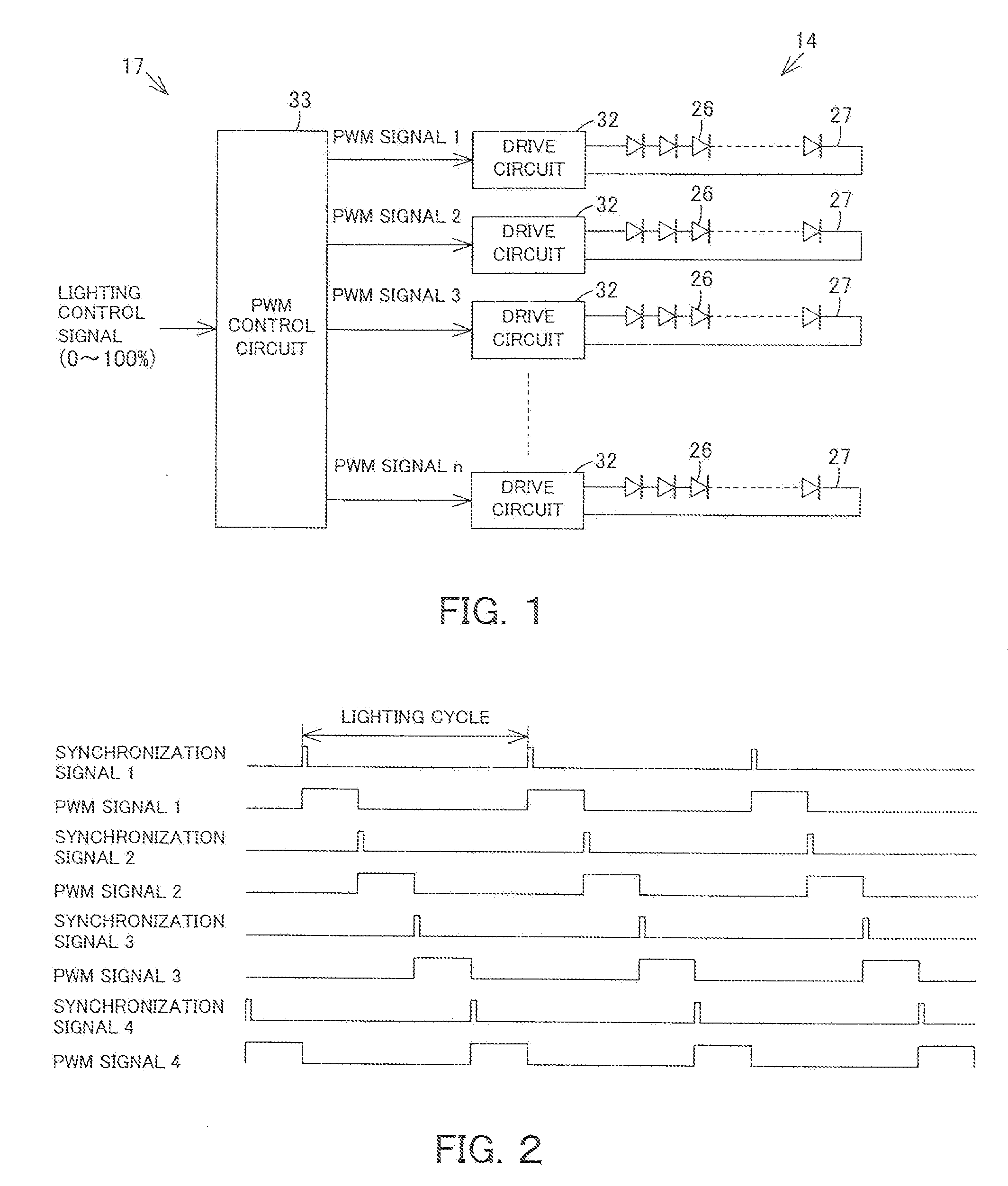
[0015]Thus, since the output timings of the PWM signals are made different from each other per drive circuit, that is, per LED circuit by the time obtained by dividing the lighting cycle by the number of LED circuits, the period of time during which the LEDs are turned off can be shortened as the entirety of the light source portion even if the lighting control ratio is lowered, wherein changes in the brightness are reduced, and the occurrence of flickering can be reduced.
[0017]Thus, since the output timings of the PWM signals different per drive circuit with the front side and the back side of the lighting cycle separate from each other, the period of time during which the LEDs are turned off can be shortened as the entirety of the light source portion even if the lighting control ratio is lowered, wherein changes in the brightness are reduced, and the occurrence of flickering can be reduced.
[0019]Thus, since the output timings of the PWM signals are made different per drive circuit, that is, per LED circuit in a range in which the lighting control ratio is lower than the predetermined lighting control ratio, occurrence of flickering can be reduced in a range having a low lighting control ratio, in which the brightness easily changes.

Problems solved by technology

In the PWM control system, while the PWM control system has such a feature that no color temperature of the LEDs changes in lighting control, a problem occurs that flickering by which the brightness of picked-up pictures changes is brought about due to a difference between the vertical frequency of a television camera and the lighting frequency of the LEDs when being picked up by a television camera, in particular, when the lighting control ratio is low.
However, although flickering has conventionally been prevented from occurring by increasing the lighting frequency for PWM control, there is a problem that the component configuration becomes expensive because, in order to increase the lighting frequency for the PWM control, it is necessary to increase the capacity of the CPU of the control circuit and to improve the response efficiency of a drive circuit to drive the LEDs.
Also, since the lighting cycle is shortened by increasing the lighting frequency for the PWM control, there is another problem that it becomes difficult to enlarge the number of gradations for the PWM control and it becomes impossible to smoothly control lighting of the LEDs.

Method used


Image

  • Illumination device
  • Illumination device
  • Illumination device

Examples


Embodiment Construction

[0027]Hereinafter, a description is given of embodiments of the invention with reference to the drawings.

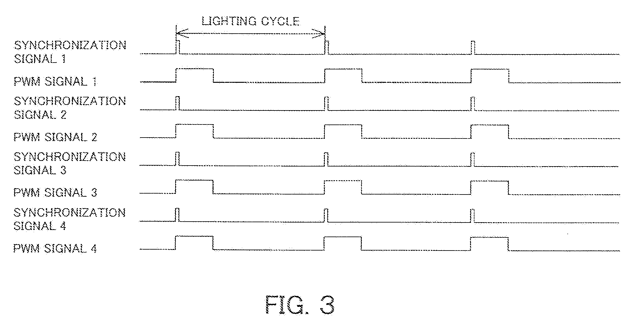
[0028]FIG. 1 through FIG. 5 show Embodiment 1. FIG. 1 is a circuit diagram of an illumination device, FIG. 2 is a timing chart in which the output timings of PWM signals are made different from each other by PWM control of the illumination device, FIG. 3 is a timing chart showing a case where the output timings of the PWM signals are the same, as a comparative example of the PWM control of the illumination device, FIG. 4 is a configurational view of the illumination device, and FIG. 5 is a front elevational view of a light source portion of the illumination device.

[0029]As shown in FIG. 4, an illumination device 11 is a spot light which is provided with a light source unit 12 for emitting light, and a projection unit 13 for projecting light emitted from the light source unit 12.

[0030]The light source portion 12 includes a light source portion 14 being a plane-shaped light, source...


PUM


Abstract

The light source portion is provided with a plurality of LED circuits having a plurality of LEDs. A plurality of drive circuits are provided which cause the LEDs to be lit per LED circuit in response to input of PWM signals. The PWM control circuit outputs PWM signals per drive circuit in response to input of lighting control signals and simultaneously make the output timings of the PWM signals different from each other per drive circuit. By making the output timings of the PWM signals different, the period of time during which the LEDs are turned off can be reduced as the entirety of the light source portion, and the occurrence of flickering is reduced without increasing the lighting frequency.

Description

INCORPORATION BY REFERENCE[0001]The present invention claims priority under 35 U.S.C. §119 to Japanese Patent Application No. 2009-115892 filed on May 12, 2009. The contents of these applications are incorporated herein by reference in their entirety.FIELD OF THE INVENTION[0002]The present invention relates to an illumination device using LEDs as a light source.BACKGROUND OF THE INVENTION[0003]As an illumination device which is used in a television studio and a theater, an illumination device which controls lighting by using LEDs as its light source has been developed.[0004]In LED lighting control, there have been used a current control system which varies a current value with an electric current flown to LEDs at all times as described in, for example, Japanese Laid-Open Patent Publication No. 2008-210537, and a PWM (Pulse Width Modulation) control system which varies the period of time during which an electric current is flown to LEDs with the current value constant.[0005]In the PW...

Claims


Application Information

Patent Timeline
Patent Type & Authority Applications(United States)
IPC IPC(8): H05B37/02H05B44/00
CPCG09G3/3406G09G2320/0247H05B33/0827H05B33/0818G09G2320/064H05B45/46H05B45/325H05B45/59
Inventor TAKASAKA, KEITAROMIGITA, KOJI
Owner TOSHIBA LIGHTING & TECH CORP
Learn More