Position detecting device and position detecting method

a technology of position detection and position detection, which is applied in the direction of instruments, computing, electric digital data processing, etc., can solve the problem of not being able to achieve the target number, etc., and achieve the effect of simple circuit configuration and high speed

Active Publication Date: 2010-11-18
WACOM CO LTD
View PDF20 Cites 24 Cited by
  • Summary
  • Abstract
  • Description
  • Claims
  • Application Information

AI Technical Summary

Benefits of technology

[0030]By supplying a first signal and a second signal, both having the predetermined time width, to each of a first electrode and a second electrode of the signal supplying electrode, with a specific time difference shorter than the predetermined time width, an electrostatic capacity type position detecting device having a large-sized position detection surface can be achieved without having to employ a complicated circuit to, for example, divide the detection surface.
[0031]According to the present invention, it is possible to provide an electrostatic capacity type position detecting device and a position detecting method capable of performing high speed scanning with relatively simple circuit configuration.

Problems solved by technology

The time necessary for performing such an integration process will not cause serious problem if a position detecting device has a relatively small size, but it will cause obvious problems if the position detecting device is large.
Accordingly, such a target number can not be achieved if the position detecting device is made using the technologies known in the prior art.

Method used


Image

  • Position detecting device and position detecting method
  • Position detecting device and position detecting method
  • Position detecting device and position detecting method

Examples


Embodiment Construction

)

[0038]Embodiments of the present invention will be described below with reference to FIGS. 1 to 5J.

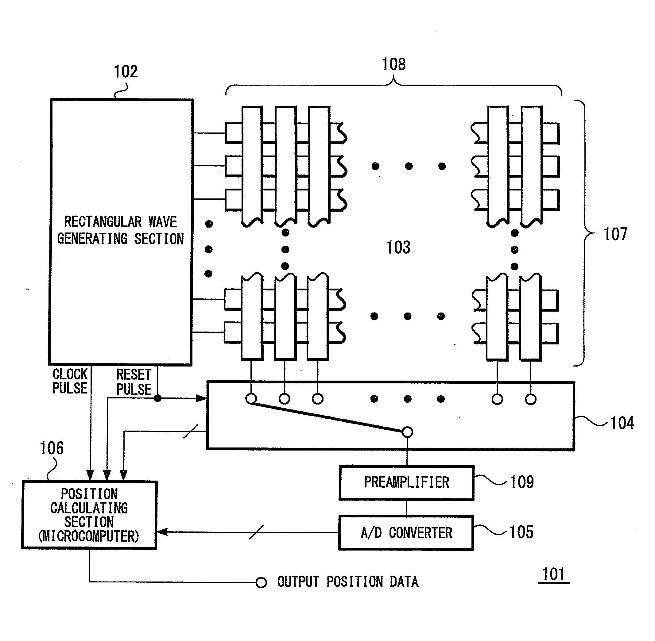
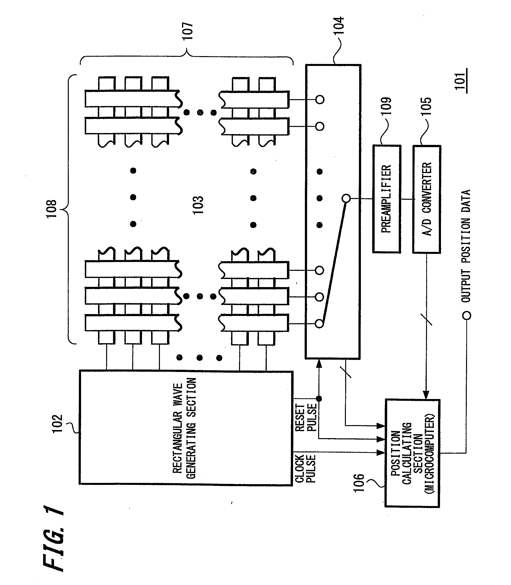
[0039]FIG. 1 is an entire block diagram showing a position detecting device 101 according to an embodiment of the present invention. The position detecting device 101 includes a rectangular wave generating section 102, a matrix electrode 103 connected to the rectangular wave generating section 102, a reception selection switch 104 connected to the matrix electrode 103, a preamplifier 109 connected to the reception selection switch 104, an A / D converter 105 connected to the preamplifier 109, and a position calculating section 106 connected to the A / D converter 105.

[0040]The rectangular wave generating section 102 is a signal supplying section for supplying a one-shot pulse voltage, which has a rectangular waveform, to the matrix electrode 103 (which is to be described later). In addition to the voltage of the one-shot pulse, the rectangular wave generating section 102 generates a clock...


PUM


Abstract

An electrostatic capacity type position detecting device having increased scanning speed is provided. The device includes a signal supplying electrode including a plurality of electrodes arranged in parallel with each other in a first direction, and a receiving electrode also including a plurality of electrodes arranged in parallel with each other in a second direction perpendicular to the first direction. A one-shot pulse having a predetermined time width is applied sequentially to the plurality of electrodes of the signal supplying electrode at a frequency equal to an integral multiple of 200 kHz. In other words, the sequential application of the one-shot pulse occurs with a time difference that is shorter than (e.g., 1/N of) the predetermined time width. A current change caused at rising and falling edges of the one-shot pulse is detected through the receiving electrode, to thereby indicate a position on the position detecting device.

Description

CROSS REFERENCES TO RELATED APPLICATIONS[0001]The present invention claims priority under 35 U.S.C. §119 from Japanese Patent Application JP 2008-203325, filed in the Japanese Patent Office on Aug. 6, 2008, the entire contents of which being incorporated herein by reference.BACKGROUND OF THE INVENTION[0002]1. Field of the Invention[0003]The present invention relates to a technique preferably applied to a position detecting device.[0004]More particularly, the present invention relates to a technique for improving the scanning speed of an electrostatic capacity type position detecting device.[0005]2. Description of the Related Art[0006]There are various kinds of input devices for providing position information to a computer. Such input devices include a kind of two-dimensional position information input device called “touch panel”.[0007]The touch panel is an input device for operating a computer and the like by a user touching a flat detection surface thereof with an input tool such a...

Claims


Application Information

Patent Timeline
Patent Type & Authority Applications(United States)
IPC IPC(8): G06F3/041
CPCG06F3/044G06F3/0416G06F3/04166G06F3/0446
Inventor MATSUBARA, MASAKI
Owner WACOM CO LTD
Why Eureka
Try Eureka