

Imaging device, imaging method, and program
a technology of imaging device and imaging method, applied in the direction of still video camera, color television details, television system, etc., to achieve the effect of stable and continuous photographing operation
- Summary
- Abstract
- Description
- Claims
- Application Information
AI Technical Summary
Benefits of technology
Problems solved by technology
Method used
Image

Examples
exemplary embodiment 1
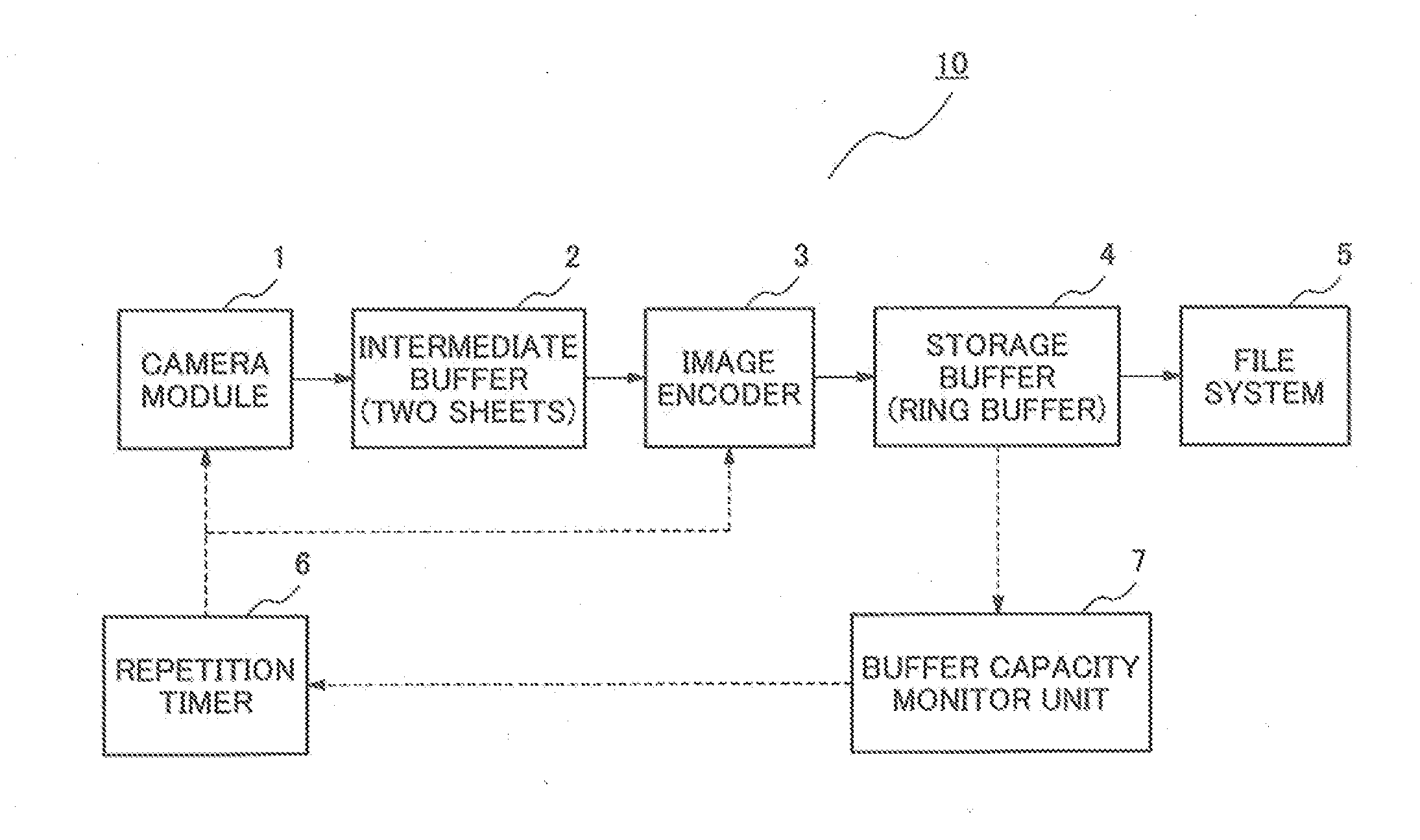
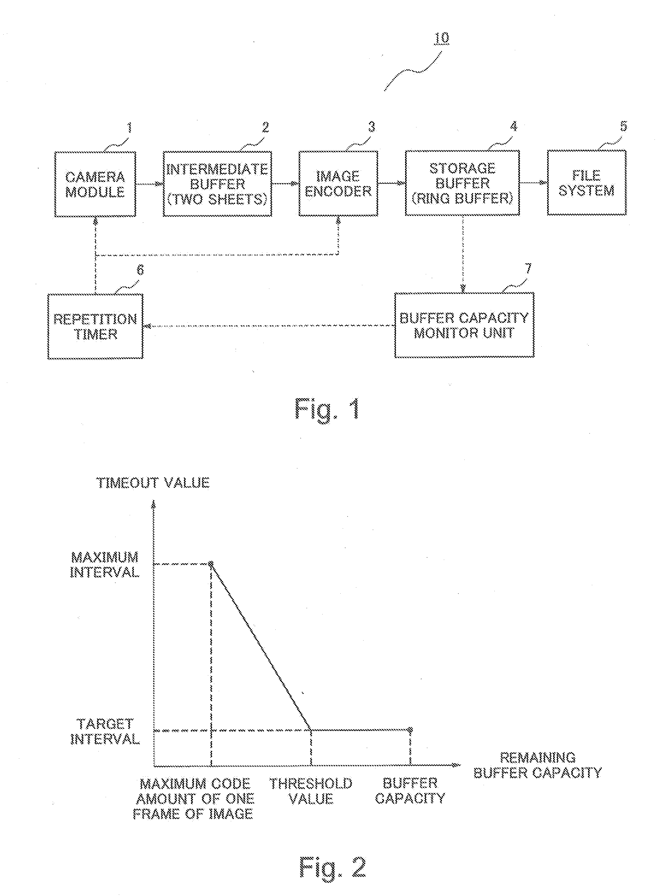
[0035]FIG. 1 is a block diagram showing a configuration of an imaging device 10 according to an exemplary embodiment 1 of the present invention. As shown in FIG. 1, the imaging device 10 includes a camera module 1, an intermediate buffer (a second buffer) 2, an image encoder 3, a storage buffer (a first buffer) 4, a file system 5, a repetition timer 6 and a buffer capacity monitor unit 7. A function of each unit is shown below.
[0036]The camera module 1 photographs an image of an object as a still image and generates image data (digital data). When the continuous photographing is performed, the camera module 1 starts each photographing operation in response to an instruction from the repetition timer 6.
[0037]The intermediate buffer 2 is a memory in which the image data generated by the camera module 1 is temporarily stored. The intermediate buffer 2 has two sheets of memory. The continuous image data can be alternately stored in the two sheets of memory.
[0038]The image encoder 3 enco...
exemplary embodiment 2
[0086]Each function block and each processing operation shown in the above-mentioned exemplary embodiment 1 can be configured by hardware as mentioned above and can be realized by computer control using a CPU (Central Processing Unit), a ROM (Read Only Memory), a RAM (Random Access Memory), and the like.
[0087]FIG. 6 is a block diagram showing a configuration of an imaging device 20 that is controlled by the computer. The imaging device 20 includes a camera module 21, an intermediate buffer 22, an image encoder 23, a storage buffer 24, a file system 25, a control unit (CPU) 26, an operation unit 27, and a ROM 28. The camera module 21 has the continuous photographing function. The intermediate buffer 22 and the storage buffer 24 can be configured by the storage area of the RAM or the like. The image encoder 23 compresses the image data. The file system 25 writes the compressed stream into the external storage device or the like as a file. The control unit (CPU) 26 controls each unit. ...
exemplary embodiment 3
[0093]FIG. 9 is a block diagram showing a configuration of an imaging device 30 according to an exemplary embodiment 3 of the present invention. As shown in FIG. 9, the imaging device 30 according to the exemplary embodiment 3 includes a storage buffer 31 and control means 32.
[0094]The storage buffer 31 stores data. The control means 32 controls the 10. photographing interval continuously for at least a part of the photographing according to the remaining capacity of the storage buffer 31.
[0095]By this configuration, an effect in which a stable and continuous photographing operation can be realized in the imaging device 30 is obtained.
[0096]In each exemplary embodiment mentioned above, the exemplary configuration in which a buffer for storing the image data to which the imaging process has been performed is used as a target buffer with which the remaining buffer capacity is monitored in order to control the continuous photographing interval has been shown. However, a configuration i...
PUM
 Abstract
Description
Claims
Application Information