Color image display device, color filter substrate, color pixel array substrate, and electronic device

a color image display and substrate technology, applied in static indicating devices, instruments, non-linear optics, etc., can solve the problems of difficult to maintain color balance, and difficulty in arranging the various circuit components which operate the end portion unit pixels in much the same manner

Active Publication Date: 2010-11-18
NEC LCD TECH CORP
View PDF4 Cites 128 Cited by
  • Summary
  • Abstract
  • Description
  • Claims
  • Application Information

AI Technical Summary

Benefits of technology

[0017]With the above configurations, the end portion sub-pixels are arrayed in a direction different from that of the inner sub-pixels in accordance with a position or a shape along the outer edge of the color image display re

Problems solved by technology

However, in the case of the related technologies described in Patent Document 4, if the end portion sub-pixels 101r of the end portion unit pixel 101 is mostly covered over with the light-shielding layer 180 as shown in FIG. 21, it is difficult to maintain the color balance only by adjustment of the black matrix width etc.
Further, the related technologies described in Patent Document 5 cannot accommodate a case where the R-, G-, and B-end portion sub-pixels making up the end portion unit pixel are covered over with the light-shielding layer in an indefinite shape, because those technologies intend only to reduce the areas of those end portion sub-pixels in order to suppress coloring at the end portions in the rectangular-shaped i

Method used


Image

  • Color image display device, color filter substrate, color pixel array substrate, and electronic device
  • Color image display device, color filter substrate, color pixel array substrate, and electronic device
  • Color image display device, color filter substrate, color pixel array substrate, and electronic device

Examples


first exemplary embodiment

[0047]A description will be given in detail of the exemplary embodiments of the present invention with respect to the drawings as follows.

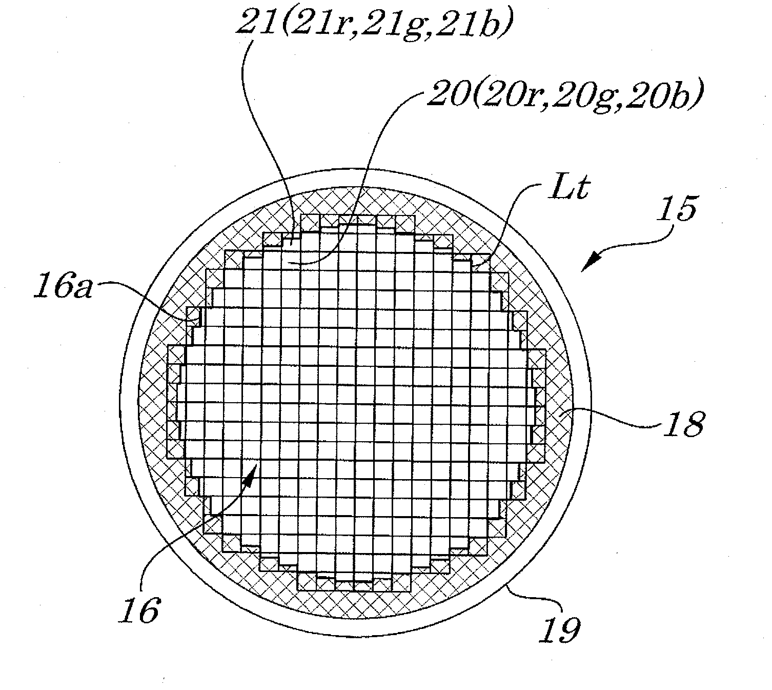
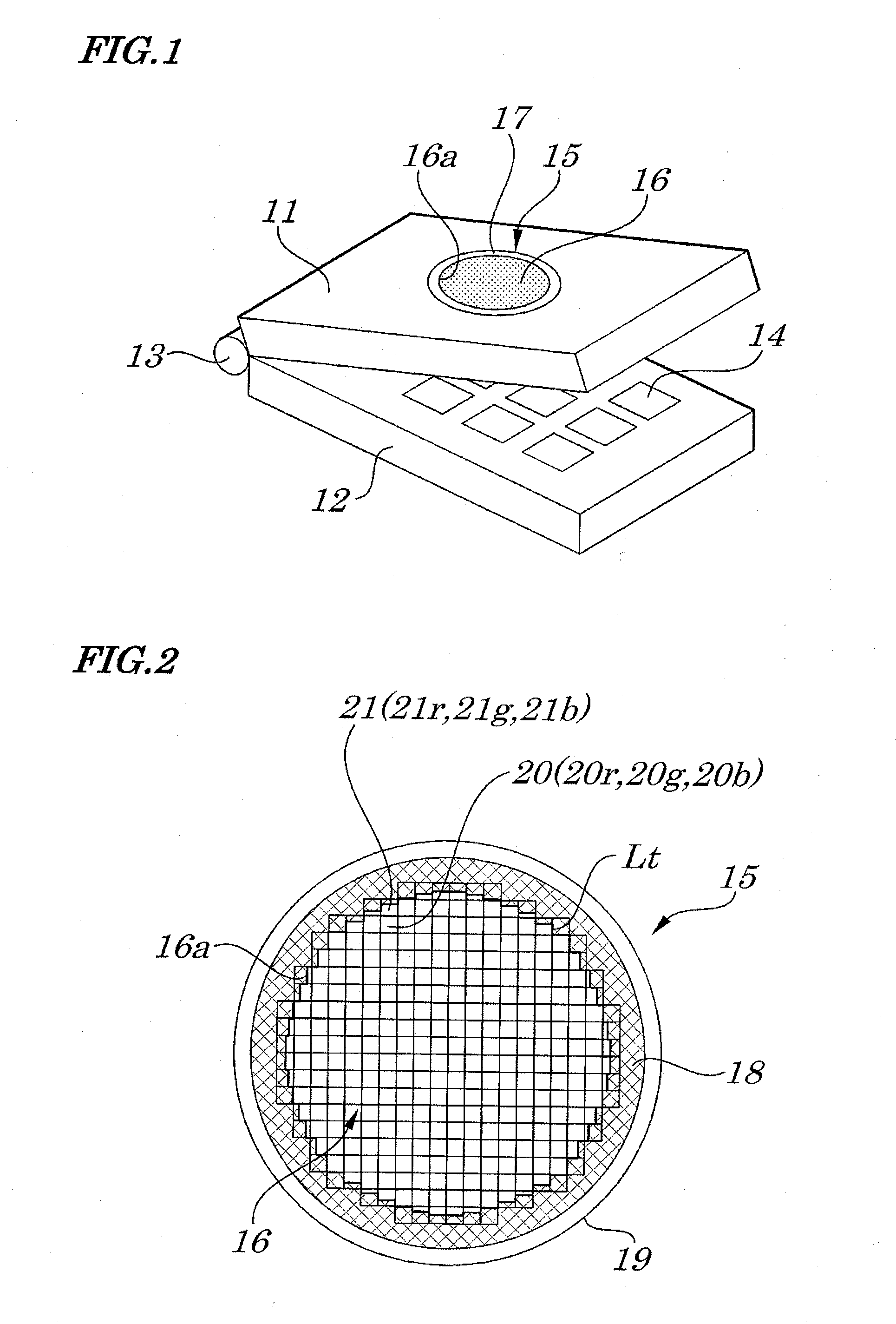
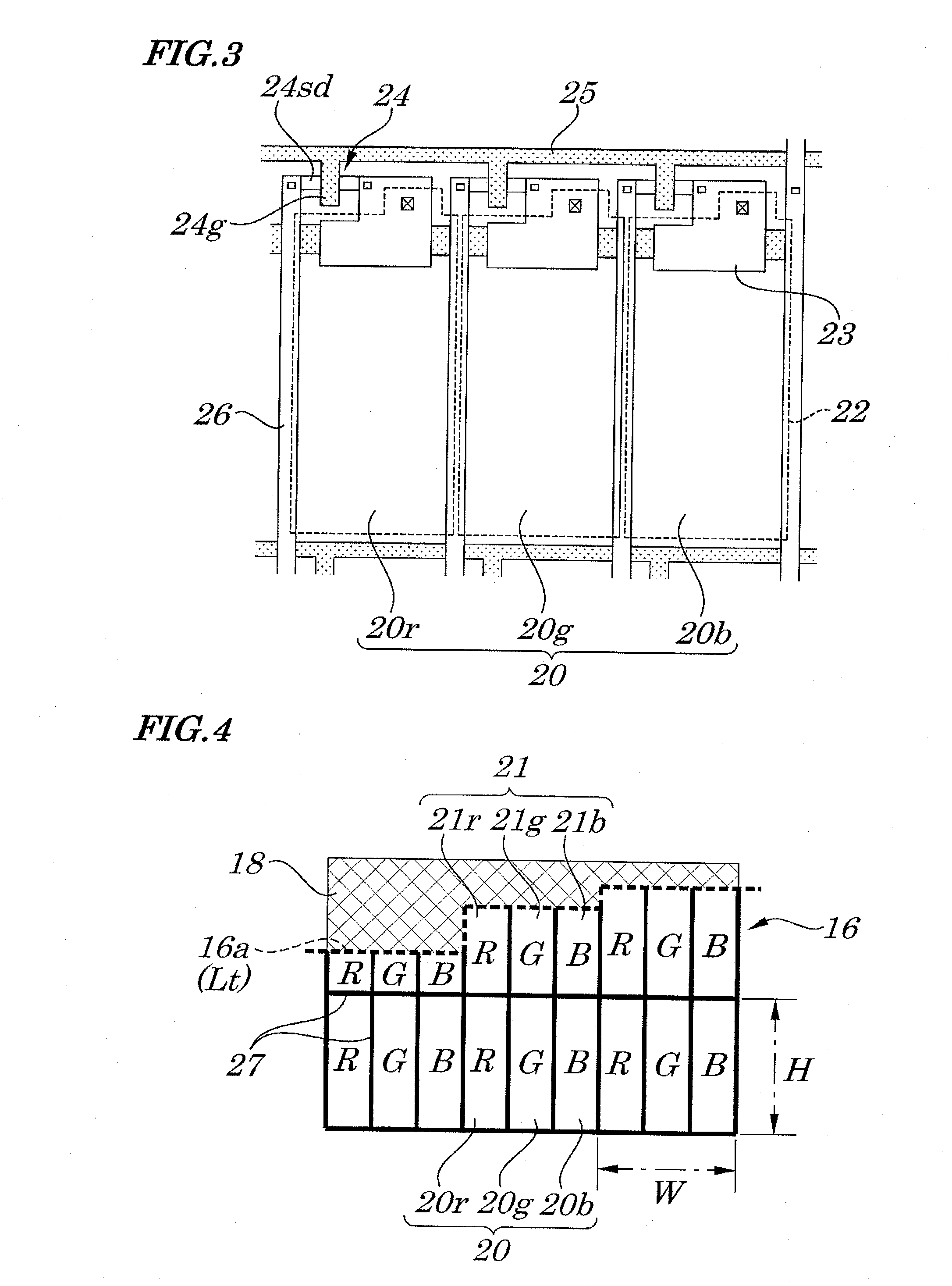
[0048]FIG. 1 is a perspective view for showing the outer appearances of a cellular phone on which to mount an image display device according to the first exemplary embodiment of the present invention, FIG. 2 is a plan view for showing an image display region of the image display device, FIG. 3 is a partially enlarged plan view for showing a layout of a circuit region and a pixel region on a color filter substrate of the image display device, FIG. 4 is a partially enlarged plan view for showing one enlarged portion of a pixel arrangement around one end portion of the image display region of the image display device, and FIG. 5 is a partially enlarged plan view for showing a pixel arrangement around another end portion of the image display region of the image display device.

[0049]The cellular phone (electronic device) of the present exemplary embodi...

second exemplary embodiment

[0058]Next, a description will be given of the second exemplary embodiment of the present invention.

[0059]FIG. 6 is a partially enlarged plan view for showing one enlarged portion of a pixel arrangement around one end portion of an image display region of an image display device according to the second exemplary embodiment of the present invention and FIG. 7 is a partially enlarged plan view for showing a pixel arrangement around another end portion of the image display region of the image display device. It is to be noted that the present exemplary embodiment has components similar to those of the above exemplary embodiment, so that identical reference numerals are given to the identical components, and description will be given of dissimilar components (which holds true also with the other exemplary embodiments described hereinafter).

[0060]Like the above first exemplary embodiment, in a circular LCD15 of a cellular phone (electronic device) of the present exemplary embodiment, an ...

third exemplary embodiment

[0065]Next, a description will be given of the third exemplary embodiment of the present invention.

[0066]FIG. 8 is a partially enlarged plan view for showing one enlarged portion of a pixel arrangement around one end portion of an image display region of an image display device according to the third exemplary embodiment of the present invention and FIG. 9 is a partially enlarged plan view for showing a pixel arrangement around another end portion of the image display region of the image display device.

[0067]Like the above second exemplary embodiment, in a circular LCD15 of a cellular phone (electronic device) of the present exemplary embodiment, an end portion unit pixel 33 adjoining an outer edge 16a of the upper side or the lower side (not shown) of an image display region 16 in FIG. 8 has its end portion sub-pixels 33r, 33g, and 33b arrayed in the same lateral direction as the array direction of inner sub-pixels 20r, 20g, and 20b of an inner unit pixel 20. Further, the end porti...


PUM


Abstract

A color image display device is provided which is capable of displaying an image with no differences in color balance between end portions and inner portions of anon-rectangle image display region. The color image display device includes an end portion unit pixel formed in an edge portion of a display region in which a color image is displayed and including end portion sub-pixels which correspond to a plurality of kinds of primary colors respectively in a one-to-one relationship and an inner unit pixel formed in an inside of the display region with respect to the end portion unit pixels and including inner sub-pixels which correspond to the plurality of kinds of primary colors respectively in a one-to-one relationship. With such a configuration, a relative area proportion of the end portion sub-pixels that correspond to the primary colors respectively in a one-to-one relationship is set equal to that of the inner sub-pixels that correspond to the primary colors respectively in a one-to-one relationship. The plurality of kinds of the end portion sub-pixels is arrayed in accordance with a position or a shape on an outer edge of the display region, an array direction of the plurality of kinds of the end portion sub-pixels and an array direction of the plurality of kinds of the inner sub-pixels configured to intersect each other.

Description

INCORPORATION BY REFERENCE[0001]This application is based upon and claims the benefit of priorities from Japanese Patent Application No. 2009-117061, filed on May 13, 2009 and Japanese Patent Application No. 2010-097450, filed on Apr. 21, 2010, the disclosures of which are incorporated herein in its entirely by reference.BACKGROUND OF THE INVENTION[0002]1. Field of the Invention[0003]The present invention relates to a color image display device, a color filter substrate, a color pixel array substrate, and an electronic device and, more specifically to, a color image display device, a color filter substrate, a color pixel array substrate, an image display device, and an electronic device by which an outer edge of an image display region have a non-rectangular shape in part or as a whole.[0004]2. Description of the Related Art[0005]An image display device is used often in the case of outputting various kinds of display information in an image such as characters or illustrations in a c...

Claims


Application Information

Patent Timeline
IPC IPC(8): G02F1/1335
CPCG02F1/133514G02F2001/133388G02F1/1368G02F2201/56G02F2201/52G09G3/20G09G2300/0426G02F1/133388
Inventor NONAKA, YOSHIHIRO
Owner NEC LCD TECH CORP
Why Eureka
Try Eureka