
Channel switching apparatus and method of a base station and channel switching apparatus and method of a terminal based on the cognitive radio system

a channel switching apparatus and terminal technology, applied in the direction of electrical apparatus, wireless communication services, wireless commuication services, etc., can solve the problem of a relatively long initialization time, achieve the effect of reducing the service delay time period, improving system reliability, and easy satisfying the quality of servi

Active Publication Date: 2010-11-18
ELECTRONICS & TELECOMM RES INST
View PDF9 Cites 14 Cited by
  • Summary
  • Abstract
  • Description
  • Claims
  • Application Information

AI Technical Summary

Benefits of technology

[0021]According to one or more embodiments of the present invention, it is possible to improve system reliability, to significantly reduce a service delay time period and to easily satisfy a Quality of Service (QoS) by reducing an initialization time after channel switching is performed in a cognitive radio system.BEST MODE
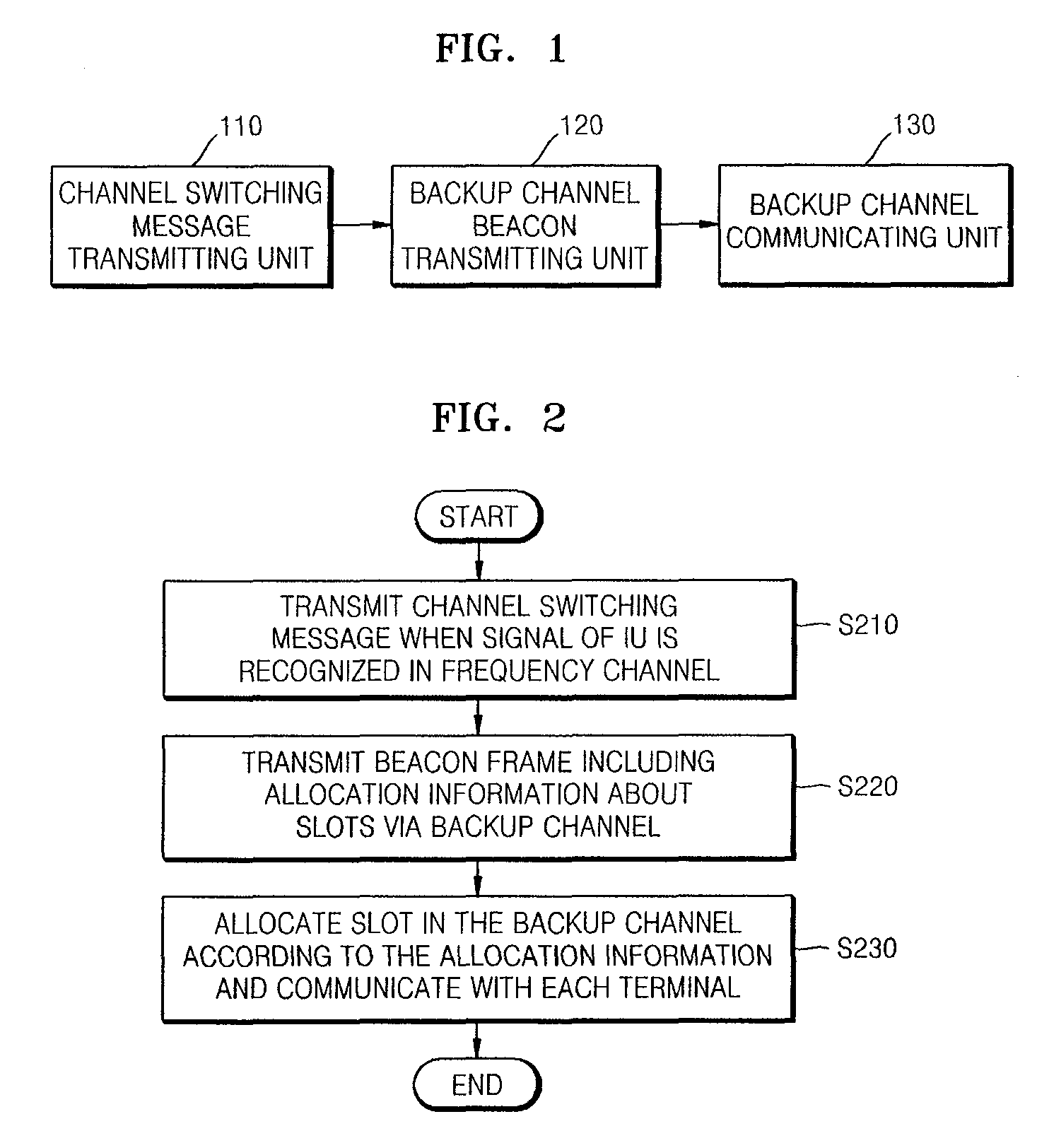
[0022]FIG. 1 is a configuration diagram of a channel switching apparatus of a base station in a cognitive radio system according to an embodiment of the present invention. FIG. 2 is a flowchart of a channel switching method performed by the base station of FIG. 1.
[0023]Concepts in regard to the base station and a terminal may also be respectively applied to a network management system (NMS) and a device in a small network such as an Ad-Hoc network in which a base station and a terminal are changed according to time with respect to their functions and are operated.
[0024]Referring to FIG. 1, the channel switching apparatus of the base station includes a channel switching message transmitting unit 110, a backup channel beacon transmitting unit 120, and a backup channel communicating unit 130.
[0025]When a signal of an incumbent user (IU) is recognized in a frequency channel that is not being used by the IU, the channel switching message transmitting unit 110 transmits a channel switching message so as to request each of a plurality of terminals to switch their communication channels to a backup channel that is predetermined for each channel (operation S210). At this time, the channel switching message may contain information indicating the predetermined backup channel.
[0026]The backup channel beacon transmitting unit 120 transmits a beacon frame via the predetermined backup channel, wherein the beacon frame includes allocation information about slots which are in the frequency channel and which are respectively allocated to each of a plurality of terminals previously (operation S220).

Problems solved by technology

However, the general initialization technique has to allow the system to be adapted to many parameters so that it takes a relatively long initialization time.

Method used


Image

  • Channel switching apparatus and method of a base station and channel switching apparatus and method of a terminal based on the cognitive radio system
  • Channel switching apparatus and method of a base station and channel switching apparatus and method of a terminal based on the cognitive radio system
  • Channel switching apparatus and method of a base station and channel switching apparatus and method of a terminal based on the cognitive radio system

Examples


Embodiment Construction

Technical Problem

[0016]The present invention provides a channel switching apparatus and method thereof performed by a base station, and a channel switching apparatus and method thereof performed by a terminal so that system reliability is improved and Quality of Service (QoS) is enhanced by reducing an initialization time after channel switching is performed in a cognitive radio system.

Technical Solution

[0017]According to an aspect of the present invention, there is provided a channel switching apparatus of a base station in a cognitive radio system, wherein the base station allocates a slot for data exchange with each of a plurality of terminals in a frequency channel which is not used by an incumbent user (IU), and performs communication, the base station including a channel switching message transmitting unit transmitting a channel switching message requesting to switch to a backup channel when a signal of the IU is sensed in the frequency channel; a backup channel beacon transmi...


PUM


Abstract

In a cognitive radio system, when communication in an operational channel is determined to be discontinued due to that an incumbent user (IU) entering the operational channel that is currently being used or due to that an excessive interference occurring in the operational channel, the operational channel is switched to a pre-arranged channel. However, since some parameters are different between the operational channel and the pre-arranged channel, an initialization procedure has to be performed to allow the cognitive radio system to be adapted to those some parameters. Since an initialization technique aiming for this situation is not developed yet, a conventional cognitive radio system uses a general initialization technique used to initially operate a system. However, the general initialization technique has to allow the system to be adapted to many parameters so that it takes a relatively long initialization time. A channel switching apparatus and method thereof of a base station, which allocates a slot for data exchange with each of a plurality of terminals in a frequency channel that is not used by the IU and thus performs communication, include transmitting a channel switching message for requesting to switch to a backup channel when a signal of the IU is sensed in the frequency channel; transmitting a beacon frame via the backup channel, wherein the beacon frame comprises allocation information about slots which are in the frequency channel and which are respectively allocated to each of the plurality of terminals; and allocating the slot for data exchange with each of the plurality of terminals to the backup channel according to the allocation information, and communicating with each of the plurality of terminals. By doing so, frequency resources between each of networks can be efficiently used, and convenience and efficiency with respect to network operation can be maximized.

Description

TECHNICAL FIELD[0001]The present invention relates to a channel switching apparatus and method thereof performed by a base station, and a channel switching apparatus and method thereof performed by a terminal so that initialization is rapidly performed in a cognitive radio system, and more particularly, to a channel switching apparatus and method thereof performed by a base station, and a channel switching apparatus and method thereof performed by a terminal so that system reliability is improved and Quality of Service (QoS) is enhanced by reducing an initialization time after channel switching is performed in a cognitive radio system.[0002]The present invention is derived from research which was supported by the ‘IT Original Technology Research and Development Program’ of the Ministry of Information and Communications (MIC), Republic of Korea [the project management number: 2005-S-002-03, and the project title: ‘Development of Cognitive Radio Technology for improving spectrum usage...

Claims


Application Information

Patent Timeline
Patent Type & Authority Applications(United States)
IPC IPC(8): H04W72/04
CPCH04W16/14H04W36/06H04W72/0446H04W72/042H04W48/12H04W72/23H04W72/20H04W72/542
Inventor KO, GWANGZEENYOU, SUNG-JINSONG, MYUNG-SUNHWANG, SUNG-HYUNUM, JUNG-SUNKIM, CHANG-JOO
Owner ELECTRONICS & TELECOMM RES INST
Learn More