
Multi-Band Gain Adaptation for Receiver Equalization Using Approximate Frequency Separation

a receiver and frequency separation technology, applied in the field of communication systems, can solve the problems of sub-optimal performance and increase the cost of the associated device, and achieve the effect of improving the equalization of the receiver, avoiding costs and performance limitations

Inactive Publication Date: 2010-11-18
LSI CORPORATION +1
View PDF9 Cites 26 Cited by
  • Summary
  • Abstract
  • Description
  • Claims
  • Application Information

AI Technical Summary

Benefits of technology

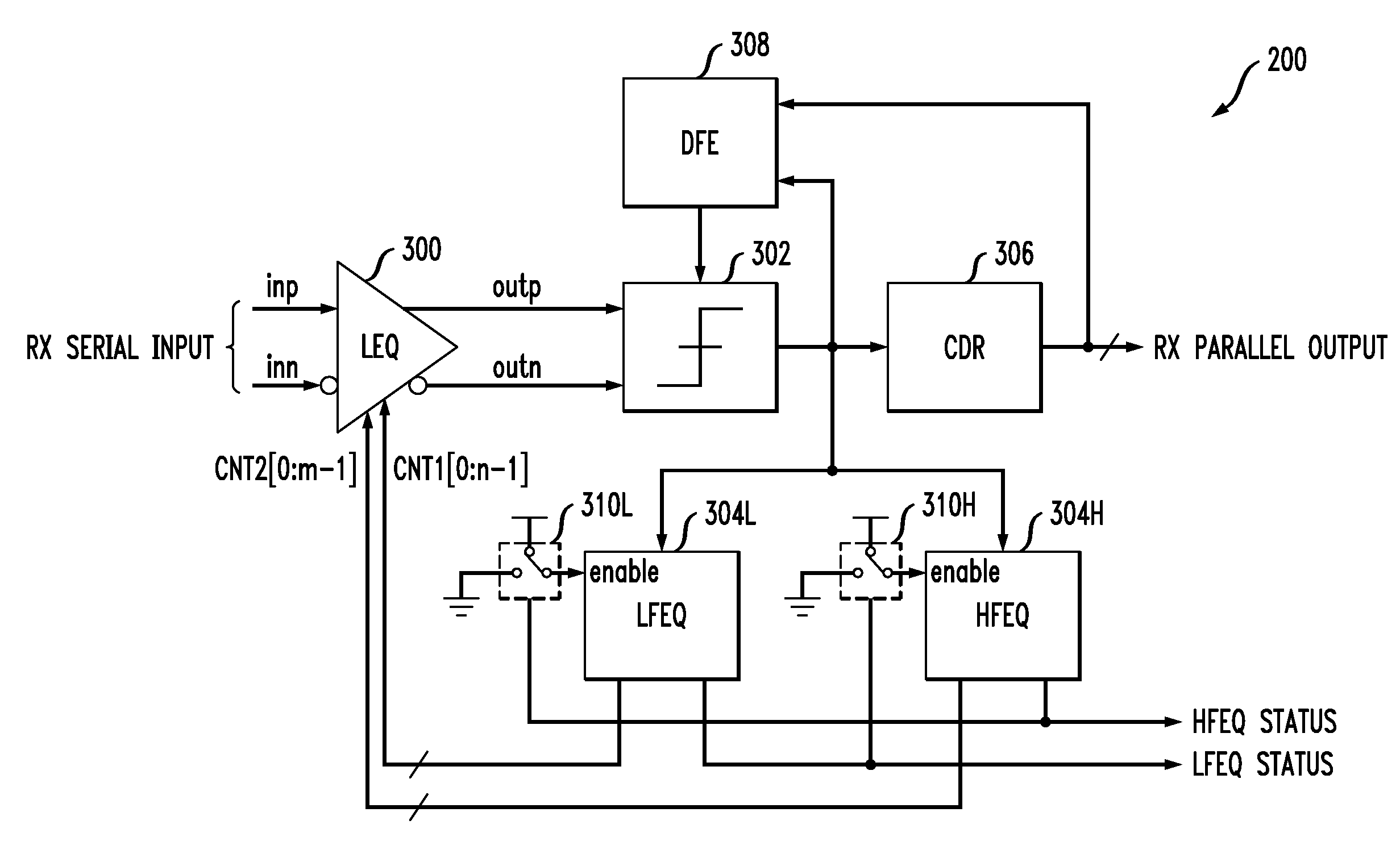
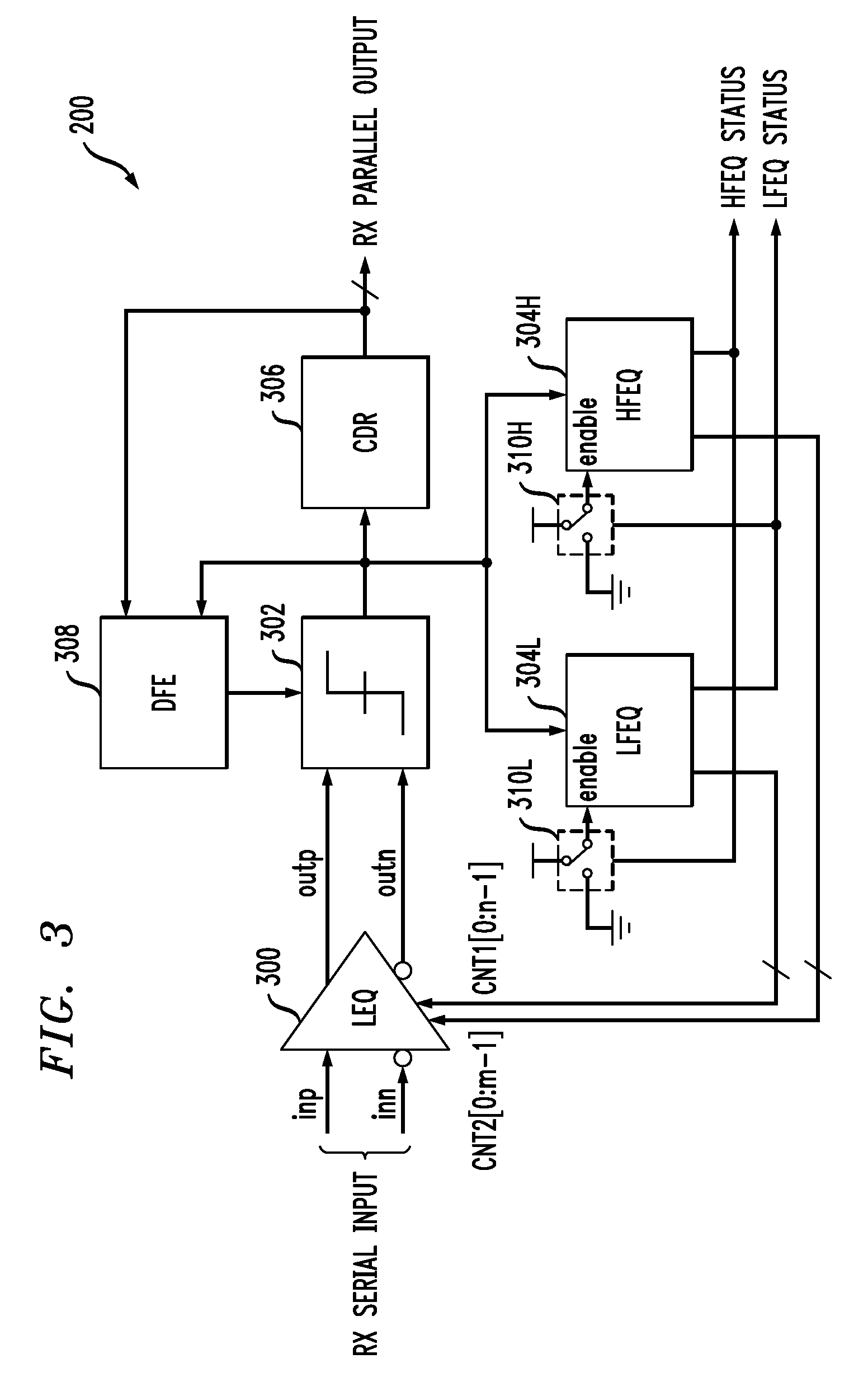
[0015]The illustrative embodiments provide improved receiver equalization relative to conventional approaches, while avoiding the costs and performance limitations commonly associated with manual tuning of LEQ parameters. For example, the self-adaptive equalization provided in the illustrative embodiments can allow a given SerDes or other communication device to operate at a higher data rate than would otherwise be possible.

Problems solved by technology

However, in arrangements such as this, it may be necessary to manually set certain LEQ parameters in the factory, which requires additional testing and thereby increases the cost of the associated device.
Also, the use of these pre-set parameters can lead to sub-optimal performance in the presence of typical variations in environmental conditions, such as voltage, temperature and link characteristics, that can arise when the device is deployed in the field.

Method used


Image

  • Multi-Band Gain Adaptation for Receiver Equalization Using Approximate Frequency Separation
  • Multi-Band Gain Adaptation for Receiver Equalization Using Approximate Frequency Separation
  • Multi-Band Gain Adaptation for Receiver Equalization Using Approximate Frequency Separation

Examples


case 1

[0112 illustrates application of SLHA to an under-equalized input data signal having a partially-closed eye diagram.

[0113]FIG. 17 shows the eye diagram of the data signal at the receiver input. It is apparent that the eye is partially closed.

[0114]FIG. 18 shows the eye diagram at the output of the LEQ using default values of 3 for both the CNT1 and CNT2 control signals.

[0115]FIG. 19 shows the eye diagram at the output of the LEQ after the performance of the low frequency gain adaptation portion of the SLHA. The roaming latch offset ΔV was set to 240 millivolts. The CNT1 signal adapts from its default value of 3 to a value of 1 using the low frequency pattern identification approximate rule 1 in the positive polarity flow (PPF) of FIG. 14. There is a noticeable envelope amplitude increase.

[0116]FIG. 20 shows the eye diagram at the output of the LEQ after the performance of the high frequency gain adaptation portion of the SLHA. The CNT2 signal adapts from its default value of 3 to a ...

case 2

[0117 illustrates application of SLHA to an input data signal with an open eye diagram.

[0118]FIG. 21 shows the eye diagram of the data signal at the receiver input.

[0119]FIG. 22 shows the eye diagram at the output of the LEQ after performance of both the low frequency and high frequency portions of the SLHA. The CNT1 and CNT2 control signals adapt from their initial default values of 3 to final values of 4.

case 3

[0120 illustrates application of SLHA to an under-equalized input data signal having a completely closed eye diagram.

[0121]FIG. 23 shows the eye diagram of the data signal at the receiver input. It is apparent that the eye is completely closed.

[0122]FIG. 24 shows the eye diagram at the output of the LEQ after performance of both the low frequency and high frequency portions of the SLHA. The CNT1 and CNT2 control signals adapt from their initial default values of 3 to final values of 7 and 15, respectively.


PUM


Abstract

A receiver comprises equalization circuitry implementing at least first and second gain adaptation loops associated with respective first and second frequency bands. The equalization circuitry in one aspect is operative to identify a pattern in a portion of a received serial data stream, and to perform gain adaptation for the receiver utilizing a particular one of the gain adaptation loops responsive to the identified pattern. For example, the gain adaptation may be performed utilizing a low frequency gain adaptation loop if the detected pattern is of a first type generally associated with a low frequency band, and may be performed utilizing a high frequency gain adaptation loop if the detected pattern is of a second type generally associated with a high frequency band. In other aspects, the first and second gain adaptation loops may be activated in a particular serial order or in parallel.

Description

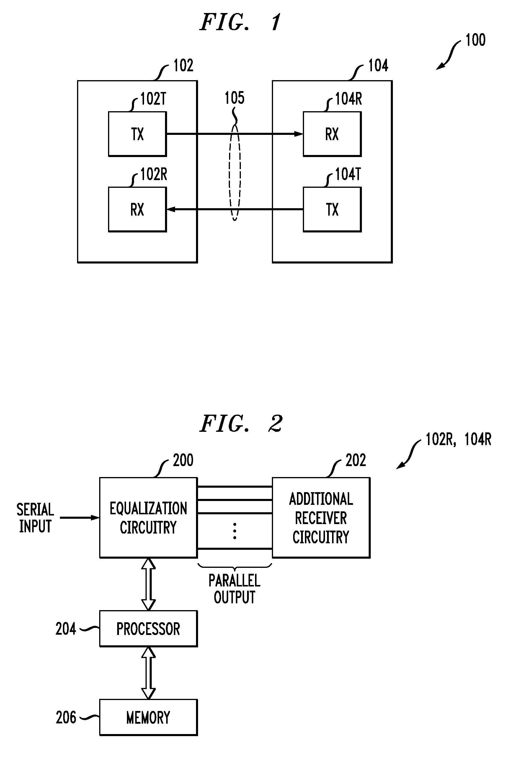
FIELD OF THE INVENTION[0001]The present invention relates generally to communication systems, and more particularly to receiver equalization circuitry utilized in such systems.BACKGROUND OF THE INVENTION[0002]Many communication system receivers incorporate equalization circuitry. For example, equalization circuitry is commonly utilized in a receiver of a high-speed serializer / deserializer (SerDes) device to mitigate the effects of inter-symbol interference (ISI) caused by transmission over a bandwidth limited serial link. Such equalization circuitry may comprise a decision feedback equalizer (DFE), a linear equalizer (LEQ), or other type of equalizer, as well as combinations of multiple equalizers. Compared to a DFE, an LEQ typically exhibits reduced complexity, higher operating speed, lower power, and smaller circuit area.[0003]It is known to make an LEQ tunable in order to accommodate various operating scenarios. An example of such an arrangement is disclosed in J. Choi et al., “A...

Claims


Application Information

Patent Timeline
IPC IPC(8): H03H7/40
CPCH04L25/03057
Inventor DAI, XINGDONGJIN, WENYIOLSEN, MAX J.ZHANG, GEOFFREY
Owner LSI CORPORATION
Learn More