Plate member fastener

a plate member and fastener technology, applied in the direction of threaded fasteners, screws, fastening means, etc., can solve the problems of high precision, high cost, permanent deformation, etc., and achieve the effect of avoiding fading or softening of plastic caps or high temperature tempering

Inactive Publication Date: 2010-11-18
WANG KUO CHUNG
View PDF0 Cites 15 Cited by
  • Summary
  • Abstract
  • Description
  • Claims
  • Application Information

AI Technical Summary

Benefits of technology

[0008]The present invention has been accomplished under the circumstances in view. It is therefore an object of the present invention to provide a plate member fastener for joining metal plate members, which keeps the plastic cap,...

Problems solved by technology

This processing process requires high precision and wastes time and labor.
During processing, the cap may be compressed excessively, resulting in permanent deformation.
Directly molding the cap on the screw does not require any secondary processing process and saves much the cost.
When bon...

Method used


Image

  • Plate member fastener
  • Plate member fastener
  • Plate member fastener

Examples


Embodiment Construction

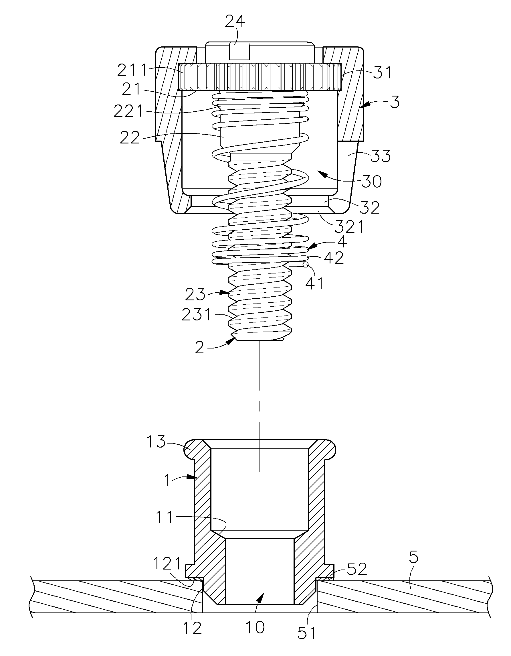
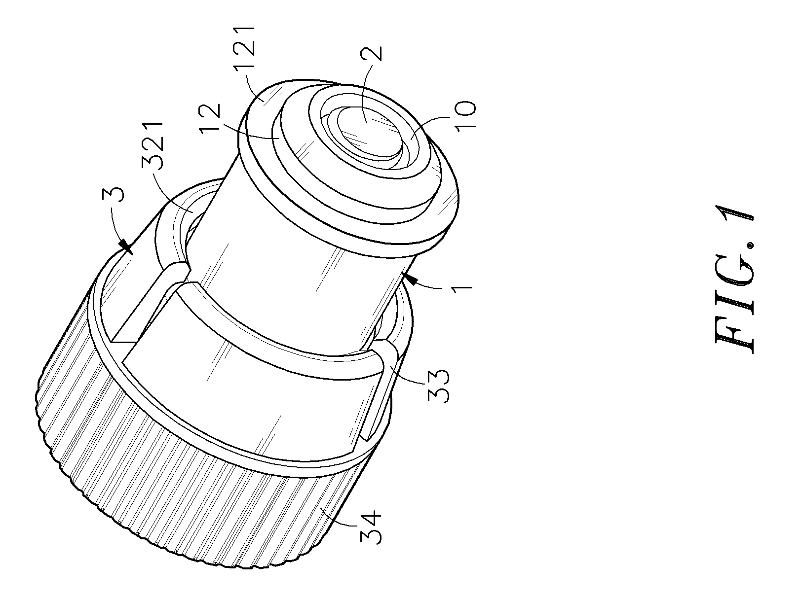
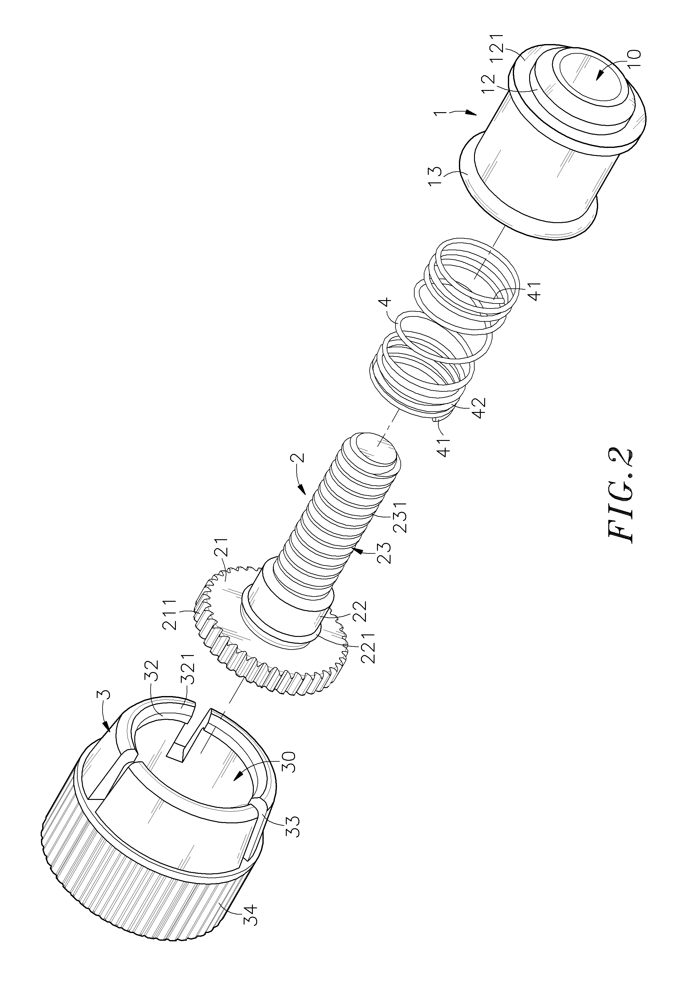
[0019]Referring to FIGS. 1˜3, a plate member fastener in accordance with a first embodiment of the present invention is shown comprising a barrel 1, a screw member 2, a cap 3, and a spring member 4.

[0020]The barrel 1 is a hollow cylindrical metal member having an inside accommodation space 10 extending through top and bottom sides thereof for accommodating the screw member 2, the cap 3 and the spring member 4, a step 11 located on the inside around the inside accommodation space 10, a top coupling flange 13 extending around the periphery of the top side, a bottom extension tube 12 axially forwardly extended from the bottom side, and a bonding flange 121 extending around the periphery of the bottom side.

[0021]The screw member 2 is a metal member having a head 21, an engagement portion 211 formed on the periphery of the head 21, a shank 23 perpendicularly extended from the center of the bottom wall of the head 21, a thread 231 spirally extending around the periphery of the shank 23, a...


PUM


Abstract

A plate member fastener includes a barrel bonded to a mounting through hole of a first metal plate member through a reflow bonding process, a screw member, which is inserted through the barrel after bonding of the barrel to the first metal plate member and threaded into a screw hole of a second metal plate member to joint the first and second metal plate members together, a cap molded on the head of the screw member and axially movably coupled to the barrel for gripping by a user to rotate the screw member into or out of the screw hole of the second metal plate member, and a spring member sleeved onto the shank of the screw member and stopped between the head of the screw member and a step inside the barrel to force the cap outwards relative to the barrel.

Description

BACKGROUND OF THE INVENTION[0001]1. Field of the Invention[0002]The present invention relates to a plate member fastener for joining two metal plate members and more particularly, to such the plate member fastener for joining a first metal plate member and a second metal plate member together, which allows bonding of the barrel thereof to the first metal plate member before installation of a screw member with an attached spring member and a cap to the barrel, preventing color fading or softening of the cap or high temperature tempering of the spring member during reflow bonding to bond the barrel to the first metal plate member.[0003]2. Description of the Related Art[0004]When fastening plate members together, a positioning screw formed of a knob, a ring and a screw nail is usually used. During installation, the screw nail and the ring are secured to the first plate member, and then the knob is rotated to drive the screw nail into the second plate member, and then a hand tool is use...

Claims


Application Information

Patent Timeline
IPC IPC(8): F16B35/02
CPCF16B5/0208
Inventor WANG, KUO-CHUNG
Owner WANG KUO CHUNG
Why Eureka
Try Eureka