Laser engraving method of plastic component

A technology of plastic parts and software, applied in the direction of engraving, decorative arts, etc., can solve the problems of short life, loss of enterprises, individuals, coating peeling, etc., to achieve the effect of short life, personalization, and increased cost

Inactive Publication Date: 2013-04-10
东莞市光威激光科技有限公司
View PDF7 Cites 12 Cited by
  • Summary
  • Abstract
  • Description
  • Claims
  • Application Information

AI Technical Summary

Problems solved by technology

Some printing materials do not meet the requirements of environmental protection, and will bring harm to the physical and mental health of consumers, and bring great losses to enterprises and individuals.
[0003] In detail, the pattern or text formed by the printing process is prone to shortcomings such as paint peeling, scratches, fading, non-wear resistance, and short life. The materials used must be environmentally friendly to meet relevant standards, and it is not suitable for personalized production; laser and The pattern or text formed by the laser marking process can realize personalized production, but because the surface or coating of the material is lasered or burned by laser, etc., the material of the outer surface is damaged, and sometimes there is a hand feeling and a depression Parts are prone to dust and dirt, and the coated ones sometimes have shortcomings such as peeling, fading, and non-wearing.
[0004] There are applications of internal engraving technology in the crystal gift industry, but they are all limited to the application of internal engraving in the field of crystal or glass, and have not been applied to large-scale industrial production applications.

Method used


Image

  • Laser engraving method of plastic component

Examples


Embodiment Construction

[0032] The operation object of this embodiment is a plastic part including at least one layer of light-transmitting material, including PC, ABS, PMMA and a mixed material of PC and ABS. The said plastic part including at least one layer of light-transmitting material means that it includes a material with a thickness of at least about 0.1 mm. It can also be a double-layer opaque material, that is, a two-color injection molding workpiece, double-layer or multi-layer lamination or bonding Composite workpiece, one or more layers of which are of any color, the outer layer is a layer of light-transmitting material, and the thickness of the light-transmitting layer can be arbitrary. The inner engraving pattern is engraved inside the light-transmitting material layer or between the transparent material layer and its adjacent two layers.

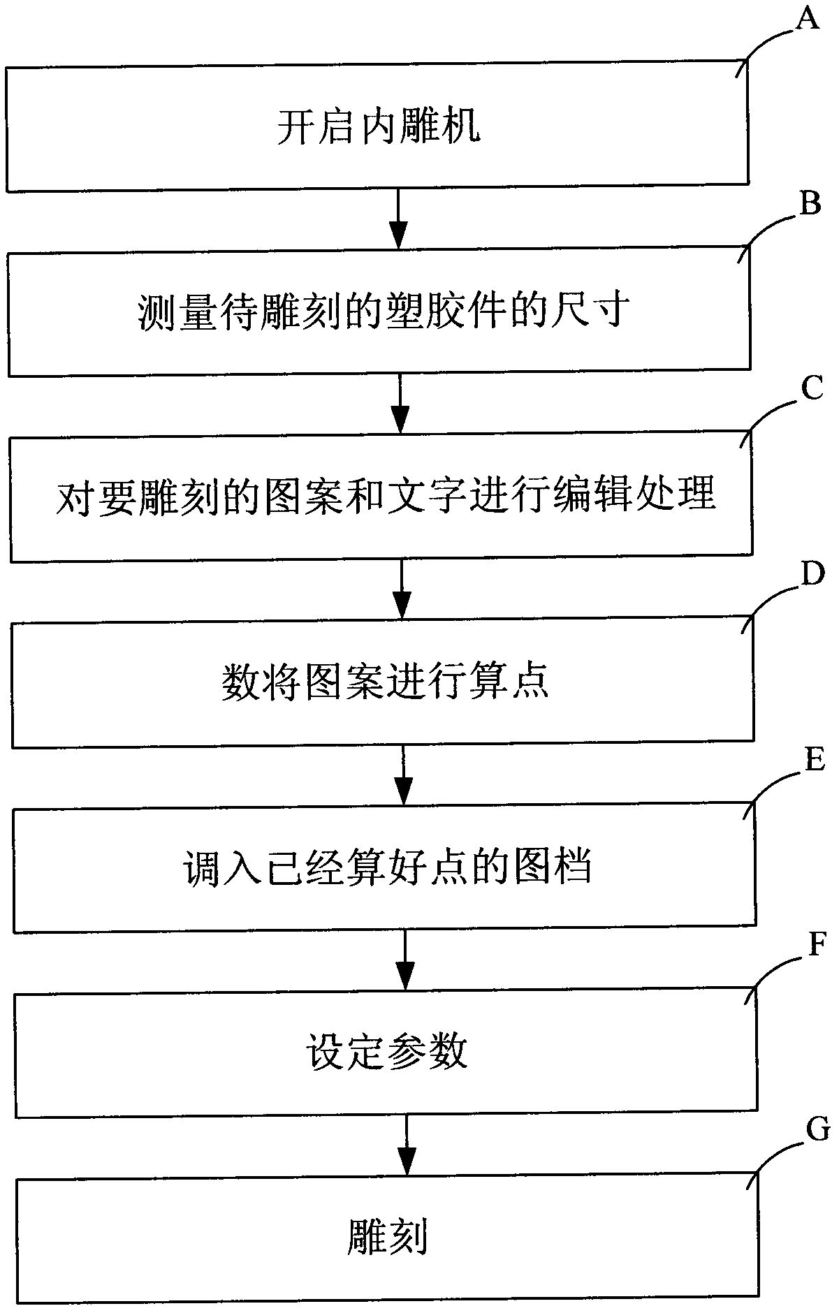
[0033] The specific steps are as follows:

[0034] The first step is to turn on the internal engraving machine and operate the equipment to the no...


PUM


Abstract

The invention relates to a laser engraving method of a product, in particular to a plastic component laser engraving method for engraving any pattern or mark in an elastic workpiece with one layer being lucent. Laser engraving is carried out inside the plastic component at least comprising one layer of transmission material. The method comprises the following steps of starting a laser engraving machine; measuring the size of the plastic component to be engraved; editing the patterns and characters; calculating points of the patterns; calling in a picture file, selecting product dimensional specification and setting parameters; and carrying out the engraving. Due to the adoption of the laser engraving method of the plastic component, not only can the display effect of the patterns and characters of the traditional process be realized, but also the defects of the traditional process such as paint dropping, dropping, color fading, non-abrasion resistance, short service life, easiness for storing dirt, environmental pollution and incapability of individualized production can be solved; and moreover, a novel high-efficient and environment-friendly technique for producing any pattern and character with no material consumption can be realized, and a broad individualized exhibition platform can be provided for the individualized times.

Description

technical field [0001] The invention relates to an internal carving method of a product, in particular to an internal carving method of a plastic part which engraves a pattern or a logo in the plastic part. technical background [0002] At present, the patterns appearing on plastic materials such as electrical shells (such as DVD panels), electrical jackets (such as mobile phone protective covers), electrical window panels (such as MP4 window lenses), and electrical buttons (such as telephone buttons, elevator buttons, computer buttons, etc.) are It is realized by printing technology, laser laser and laser marking technology, but these patterns or characters are all on the outer surface of the material. As time goes by and use, these characters or patterns will fall off, fade, wear off and other defects. Some printing materials do not meet the requirements of environmental protection, and will bring harm to the physical and mental health of consumers, and bring great losses ...

Claims


Application Information

Patent Timeline
Patent Type & Authority Applications(China)
IPC IPC(8): B44B3/02
Inventor 袁俊豪
Owner 东莞市光威激光科技有限公司
Why Eureka
Try Eureka