Spine cutter

a cutter and spine technology, applied in the field of spine cutters, can solve the problem that bone material cannot be cut out sufficiently gently

Active Publication Date: 2010-11-18
JOIMAX GMBH
View PDF19 Cites 92 Cited by
  • Summary
  • Abstract
  • Description
  • Claims
  • Application Information

AI Technical Summary

Benefits of technology

[0005]The basic object of the present invention is therefore to create improv...

Problems solved by technology

It was found that the bone material cannot be cut out sufficiently gentl...

Method used


Image

  • Spine cutter
  • Spine cutter
  • Spine cutter

Examples


Embodiment Construction

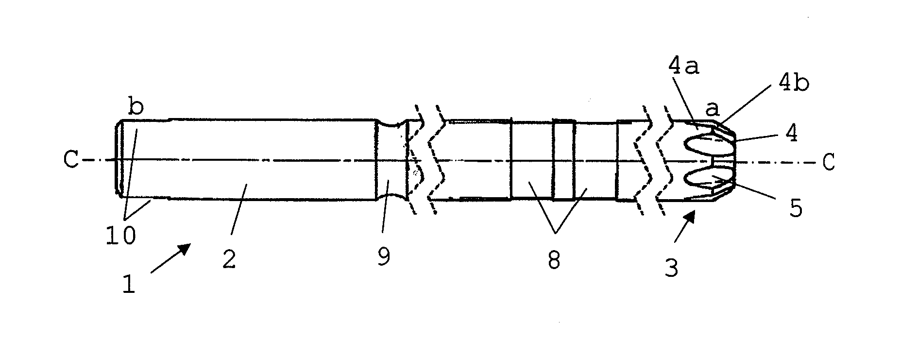
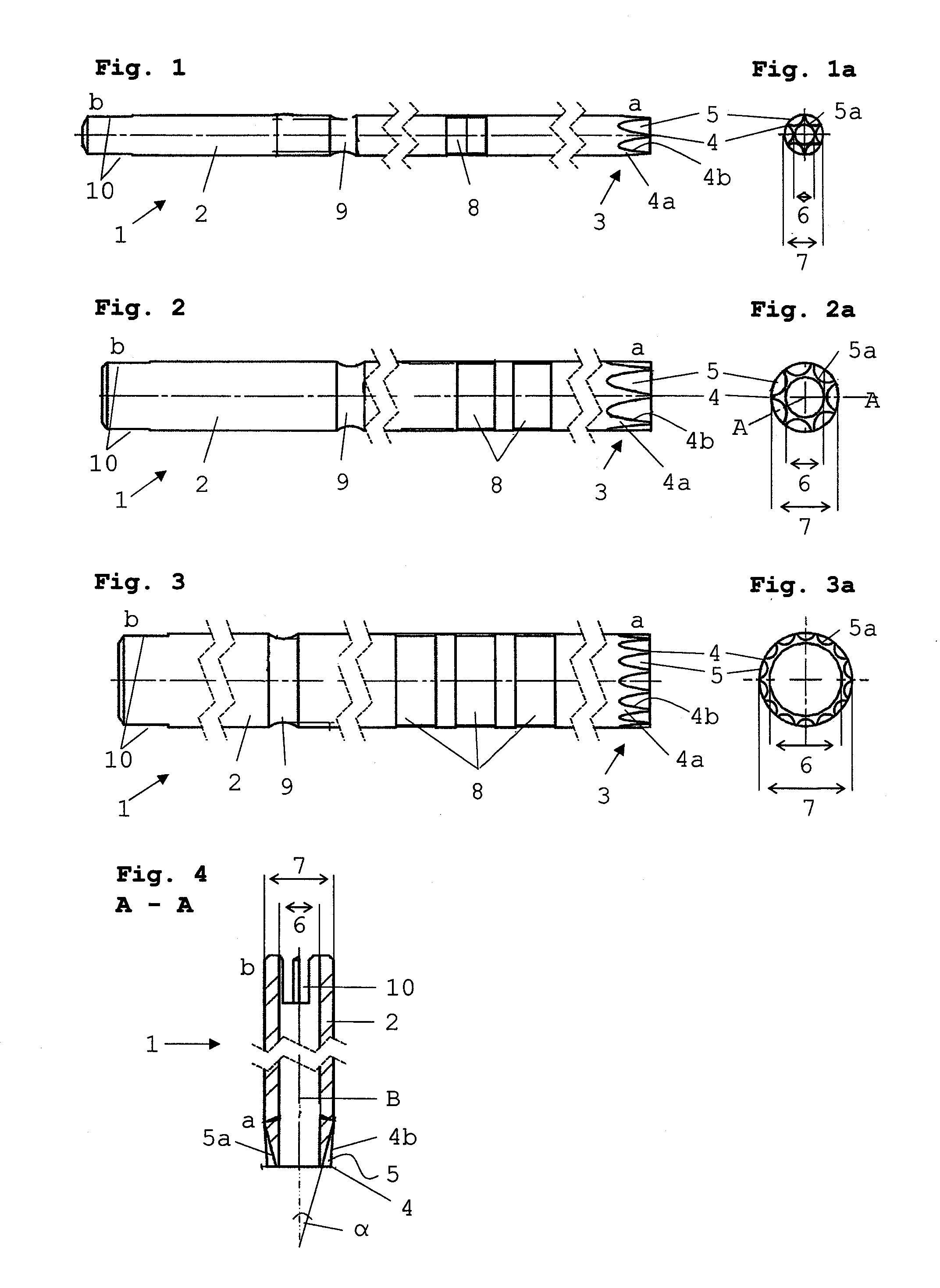
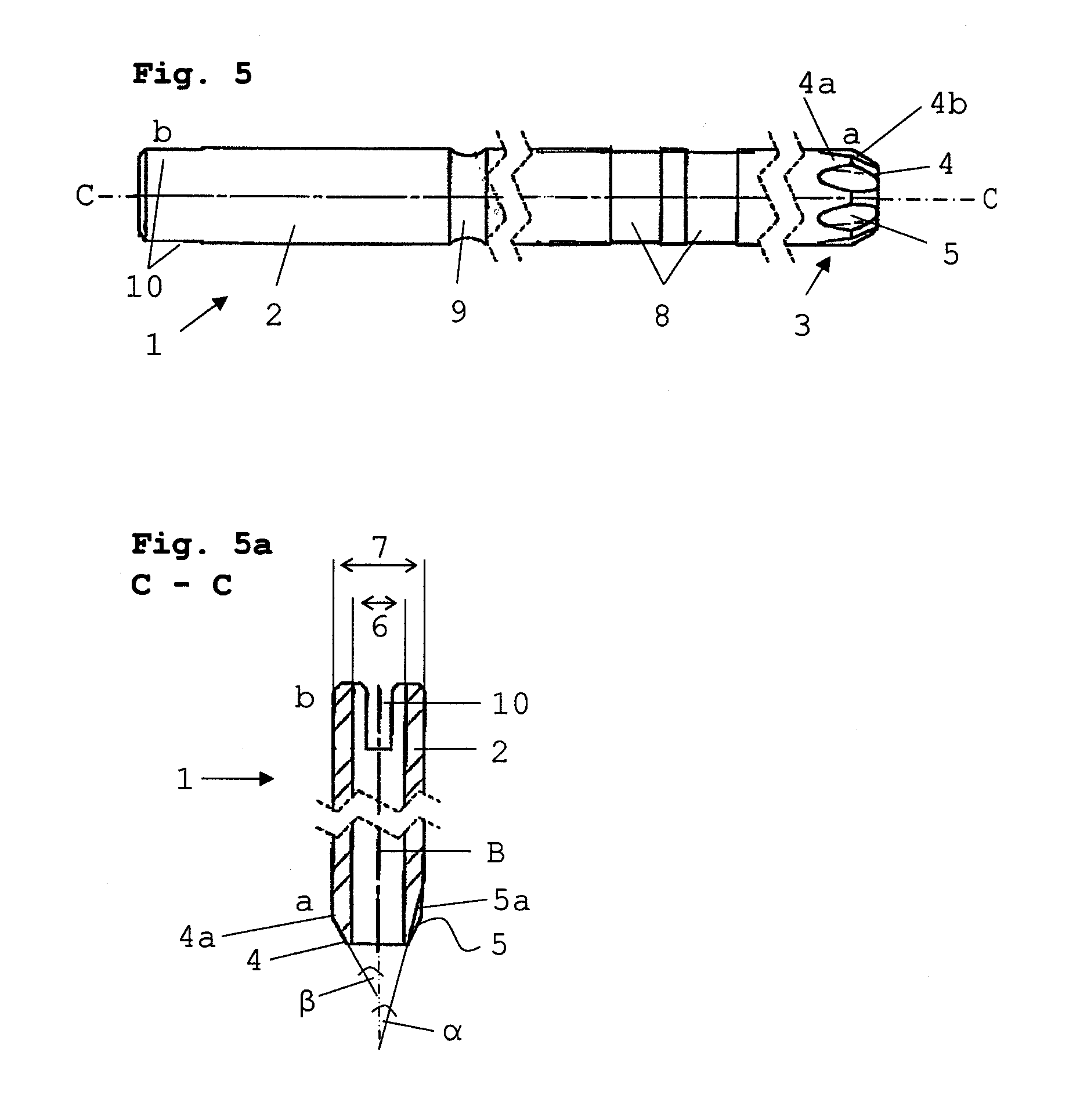
[0025]Referring to the drawings in particular, FIGS. 1, 2 and 3 show a schematic view each of cutters 1 according to the present invention and the cutters 1 together form a set of cutters 1 of different sizes. Serrated lines in the figures indicate a shortening of the length in the drawing for the sake of greater clarity.

[0026]A cutter 1, as it is shown in the exemplary embodiment according to FIG. 1 or FIG. 1a, has a cylindrical shank 2, which is formed from a long steel tube. A front-side, distal end a of cutter 1 is formed as a set of cutter teeth 3, which comprise teeth 4 and grooves 5 located between them. Grooves 5 are cut in the axial direction parabolically into the wall of shank 2, and the grooves 5 expand radially as well as axially towards the distal end a. Thus, they show a partly conical incision in the wall of shank 2. The teeth 4 are formed from the tooth walls 4a left behind after the grooves 5 have been cut out, the tooth walls 4a becoming pointed parallel to the ax...


PUM


Abstract

A cutter for spine surgery is provided, especially for use in the area of the delicate cervical spine. The cutter includes a cylindrical cutter shank with cutter teeth formed at the distal end thereof. The cutter teeth at the distal end of the cutter shank are formed by grooves in the wall of the cutter shank. The grooves become deeper and expand from the outer radius of the cutter shank towards the distal end such that teeth narrowing towards the distal end with increasing height are formed between them. This guarantees especially gentle cutting in the area of the cervical spine, without surrounding delicate tissue being additionally jeopardized.

Description

CROSS REFERENCE TO RELATED APPLICATIONS[0001]This application claims the benefit of priority under 35 U.S.C. §119 of German Patent Application DE 20 2009 006 792.0 filed May 12, 2009, the entire contents of which are incorporated herein by reference.FIELD OF THE INVENTION[0002]The present invention pertains to a cutter for spine surgery, especially for use in the area of the cervical spine, with a cylindrical cutter shank and cutter teeth formed at the distal end thereof, as well as with a cutter set comprising the aforementioned cutters.BACKGROUND OF THE INVENTION[0003]A cutter of this type is known from DE 20 2005 016 763 U1 and describes a facet joint cutter, which is used to cut out vertebral components in the area of the spine. This cutter has a cylindrical shank and sawtooth-like teeth formed at its front-side, distal end. The teeth point forward from the distal end, and said teeth are slightly expanded outwardly. The teeth are directed parallel to the axis, and grooves, which...

Claims


Application Information

Patent Timeline
IPC IPC(8): A61B17/16
CPCA61B17/1615A61B17/1671A61B17/1637A61B17/16A61B17/92A61L31/02
Inventor RIES, WOLFGANG
Owner JOIMAX GMBH
Why Eureka
Try Eureka