
In-situ upgrading of heavy crude oil in a production well using radio frequency or microwave radiation and a catalyst

a technology of radio frequency or microwave radiation and catalyst, which is applied in the direction of fluid removal, borehole/well accessories, insulation, etc., can solve the problems of reducing the activation energy required for converting and breaking down carbon-carbon bonds, water required and green house gas emissions, and hydrocarbons not typically couple well with mw radiation

Active Publication Date: 2010-11-25
CONOCOPHILLIPS CO
View PDF23 Cites 118 Cited by
  • Summary
  • Abstract
  • Description
  • Claims
  • Application Information

AI Technical Summary

Benefits of technology

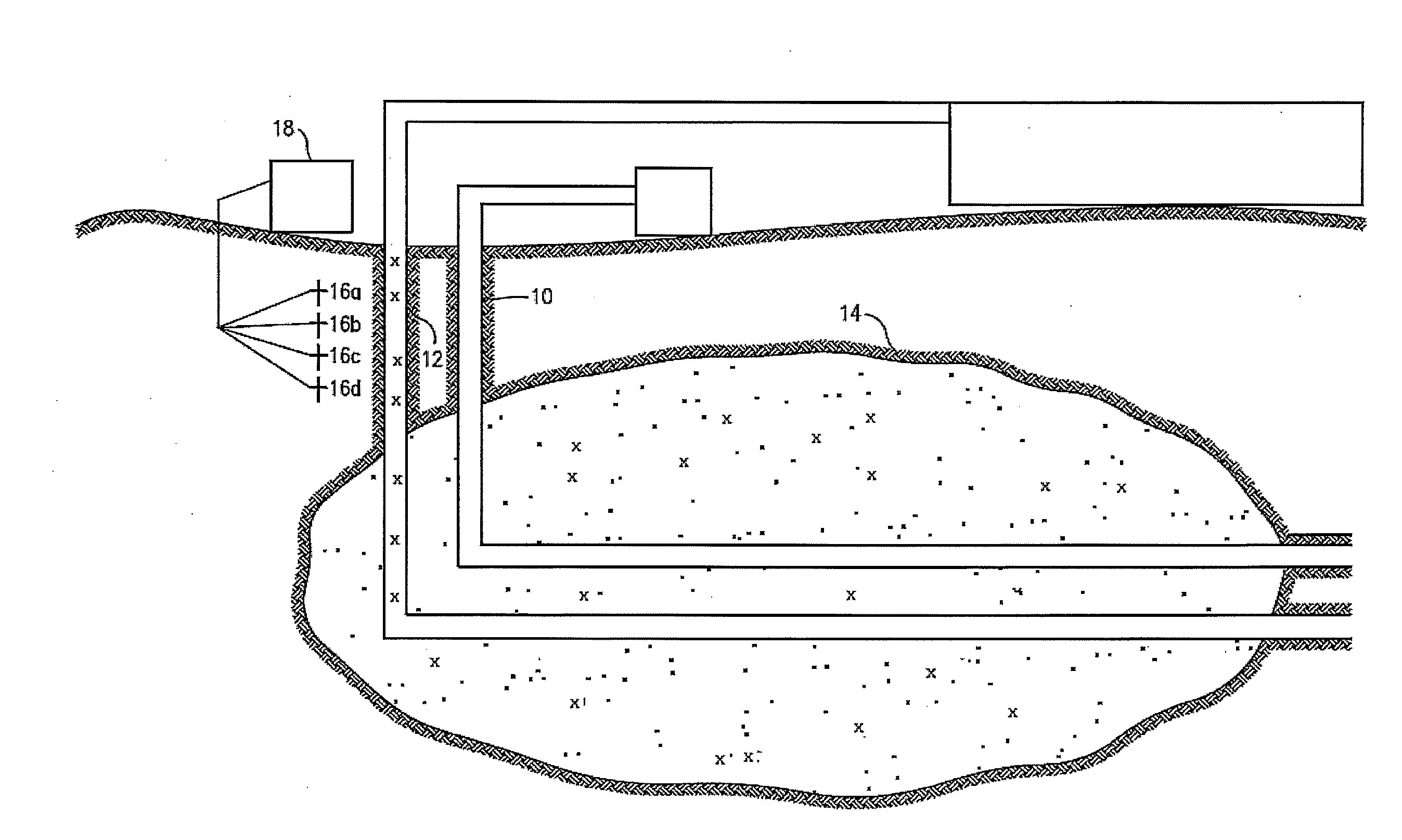
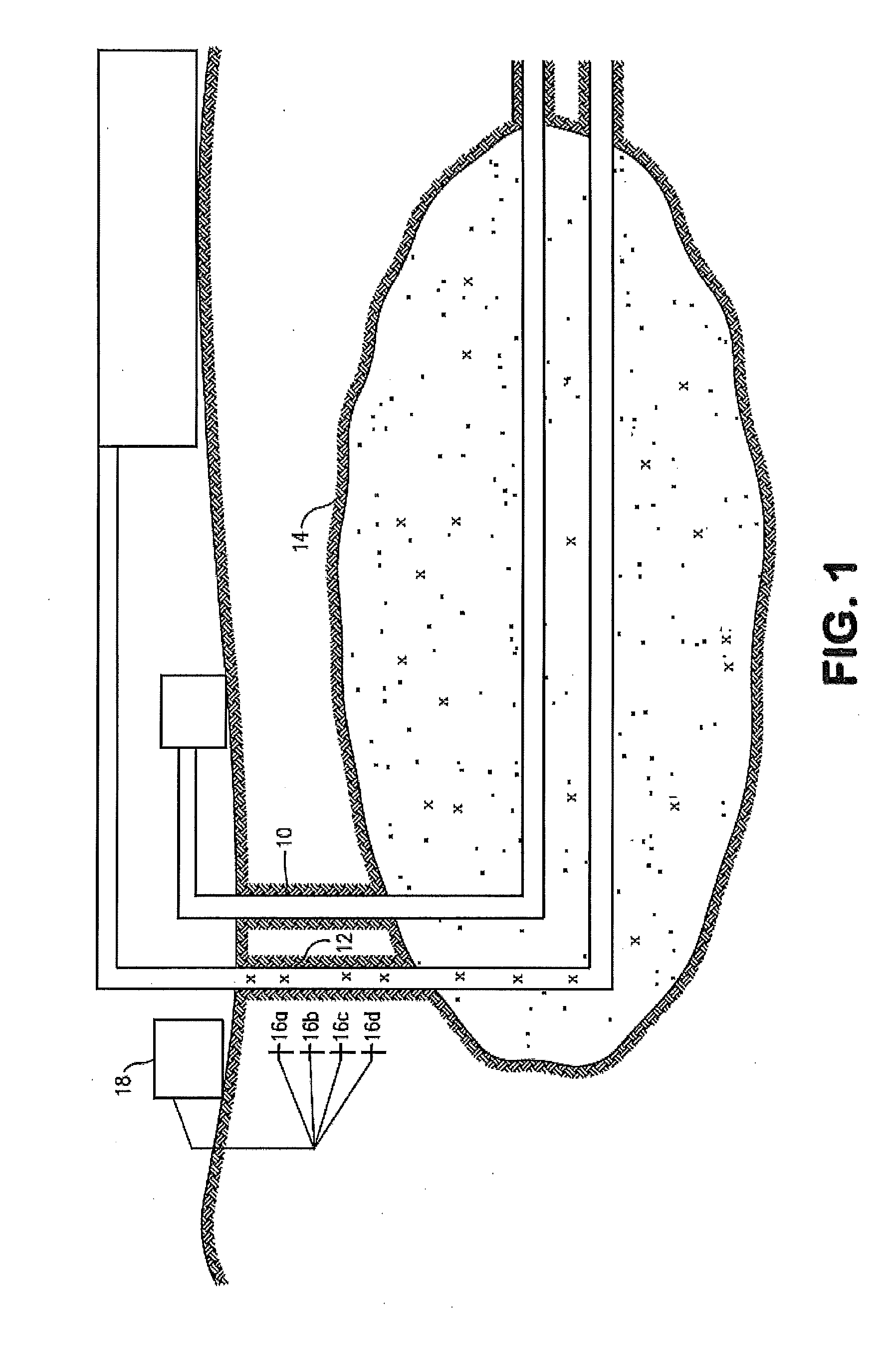
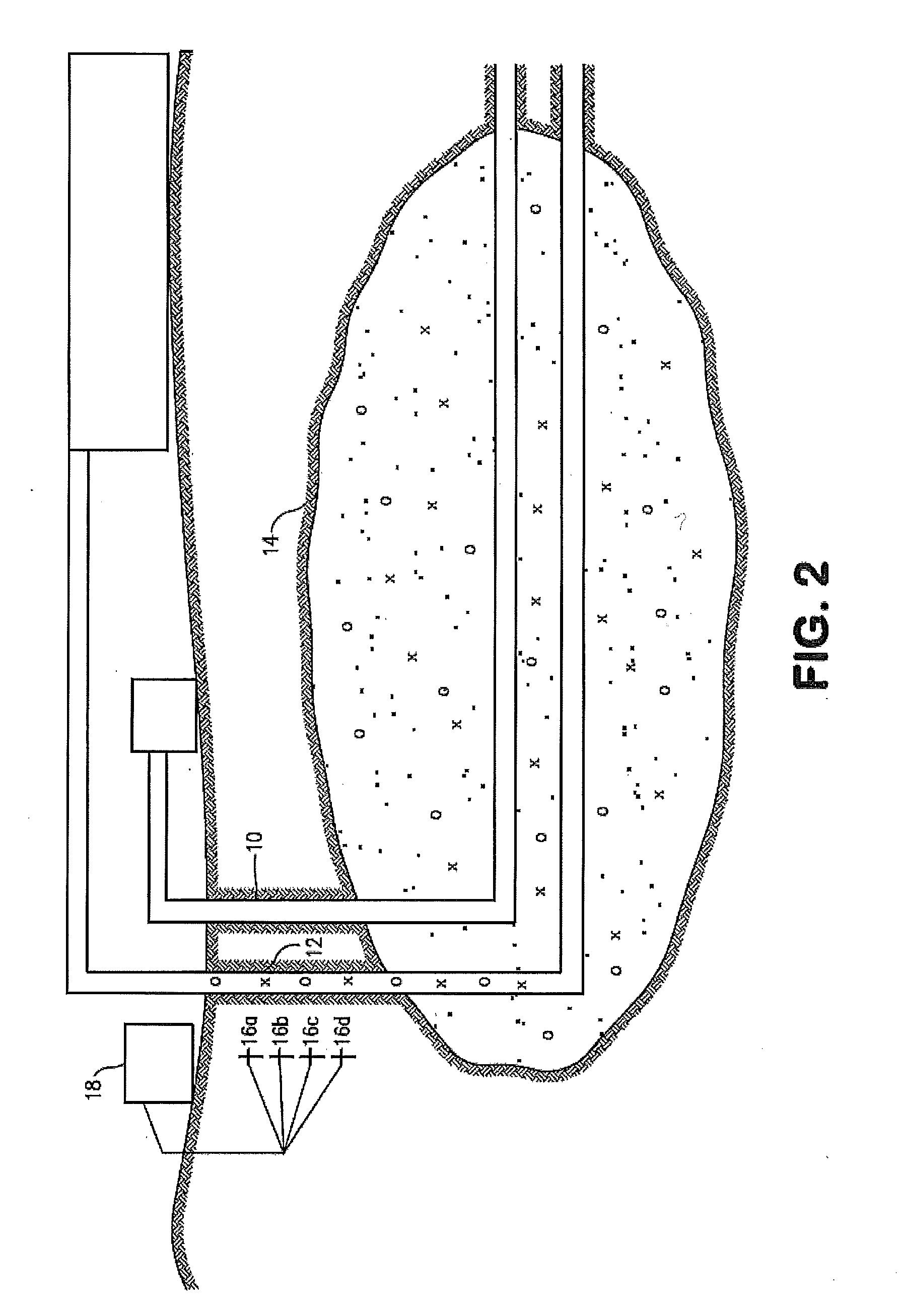
[0013]The method also teaches an alternate embodiment for upgrading heavy oil inside a production well. The method raises the subsurface temperature of heavy oil by utilizing an activator that has been injected below the surface. The activator

Problems solved by technology

Hydrocarbons do not typically couple well with MW radiation.
This may also lead to decreases in the amount of water required and green house gas emissions produced which will have positive economic and environmental impacts on operations.
Additionally, the use of MW radiation in the presence of an alternate heat source can decrease the activation energy required for converting and breaking down carbon-carbon bonds.
However, the use of RF / MW frequencies in a reservoir is not straight forward, nor is the selection of the appropriate RF / MW frequency.
Such a method decreases the ability for one to use radio frequencies over a broad area and does not eliminate the problem of selecting the appropriate radio frequency to match the multitude of chemical components within the crude oil or bitumen.
Furthermore, this method does not teach directing a radio frequency into a production well or bitumen formation to upgrade the heavy oil prior to the refinery process.
However, previous work has shown that microwave radiation alone is not sufficient to break bonds, but the activation energy associated with breaking bonds is lowered when bonds are rotated in the presence of elevated temperatures.
However use of varying radio frequencies means that there are radio frequencies generated that are not efficiently utilized.
Furthermore, this method does not teach directing a radio frequency into a production well to upgrade the heavy oil before transporting to the refinery.

Method used


Image

  • In-situ upgrading of heavy crude oil in a production well using radio frequency or microwave radiation and a catalyst
  • In-situ upgrading of heavy crude oil in a production well using radio frequency or microwave radiation and a catalyst
  • In-situ upgrading of heavy crude oil in a production well using radio frequency or microwave radiation and a catalyst

Examples


Embodiment Construction

[0018]The current method teaches the ability to upgrade heavy oil in a production well. The method first raises the temperature of heavy oil inside a production well of a steam assisted gravity drainage operation. The method also upgrades the heavy oil through the use of a catalyst to hydrogenize or desulfurize the heavy oil, injected into the production well.

[0019]During the raising of temperature of the heavy oil inside the production well activators and microwave frequencies are utilized. The temperature of the heavy oil is raised inside the production well by injecting an activator into the production well; directing a microwave frequency into the production well; exciting the activator with a microwave frequency and heating the heavy oil inside the production well with the excited activator.

[0020]By choosing specific activators to inject into the production well, one skilled in the art would have the requisite knowledge to select the exact RF / MW frequency required to achieve ma...


PUM


Abstract

A method for heating heavy oil inside a production well. The method raises the subsurface temperature of heavy oil by utilizing an activator that has been injected below the surface. The activator is then excited with a generated microwave frequency such that the excited activator heats the heavy oil.

Description

CROSS-REFERENCE TO RELATED APPLICATIONS[0001]NoneSTATEMENT REGARDING FEDERALLY SPONSORED RESEARCH OR DEVELOPMENT[0002]NoneFIELD OF THE INVENTION[0003]The in-situ upgrading of heavy crude oil using radio frequency or microwave radiation and a catalyst.BACKGROUND OF THE INVENTION[0004]Radio frequencies (RF) have been used in various industries for a number of years. One common use of this type of energy is the household cooking appliance known as the microwave (MW) oven.[0005]Microwave radiation couples with, or is absorbed by, non-symmetrical molecules or those which possess a dipole moment. In cooking applications, microwaves are absorbed by water present in food. Once this occurs, the water molecules rotate and generate heat. The remainder of the food is then heated through a conductive heating process.[0006]Hydrocarbons do not typically couple well with MW radiation. This is due to the fact that these molecules do no possess a dipole moment. However, heavy crude oils are known to ...

Claims


Application Information

Patent Timeline
IPC IPC(8): E21B43/24E21B36/00
CPCE21B43/2408
Inventor DREHER, JR., W. REIDWHEELER, THOMAS J.BANERJEE, DWIJEN K.
Owner CONOCOPHILLIPS CO
Learn More