Electrically isolated heat dissipating junction box

a junction box and heat dissipation technology, applied in the field of junction boxes, can solve the problems of “hot spots” and the limited power of photovoltaic modules, and achieve the effect of dissipating heat and dissipating hea

Active Publication Date: 2010-11-25
SOLAREDGE TECH LTD
View PDF99 Cites 161 Cited by
  • Summary
  • Abstract
  • Description
  • Claims
  • Application Information

AI Technical Summary

Benefits of technology

[0013]According to an aspect of the present invention there is provided a junction box used for making electrical connections to a photovoltaic panel. The junction box has a metal heat sink bonded in situ inside the first chamber. The first chamber is adapted to receive a circuit board for electrical power conversion, and the metal heat sink is adapted to dissipate heat generated by the circuit board. The junction box optionally may have two chambers including a first chamber and a second chamber and a wall common to and separating both chambers. Two lids adapted to seal respectively the two chambers. The metal heat sink may include a dovetail structure adapted to prevent mutual separation of the metal heat sink from the junction box. 19. The wall may have an electrical connection therethrough

Problems solved by technology

Since a single photovoltaic module can only produce a limited amount of power, commercial installations include several modules or panels interconnected in serial and in parallel into a photovoltaic array.
The shaded cells dissipate power as heat and cause “hot spots”.

Method used


Image

  • Electrically isolated heat dissipating junction box
  • Electrically isolated heat dissipating junction box
  • Electrically isolated heat dissipating junction box

Examples


Embodiment Construction

[0020]Reference will now be made in detail to embodiments of the present invention, examples of which are illustrated in the accompanying drawings, wherein like reference numerals refer to the like elements throughout. The embodiments are described below to explain the present invention by referring to the figures.

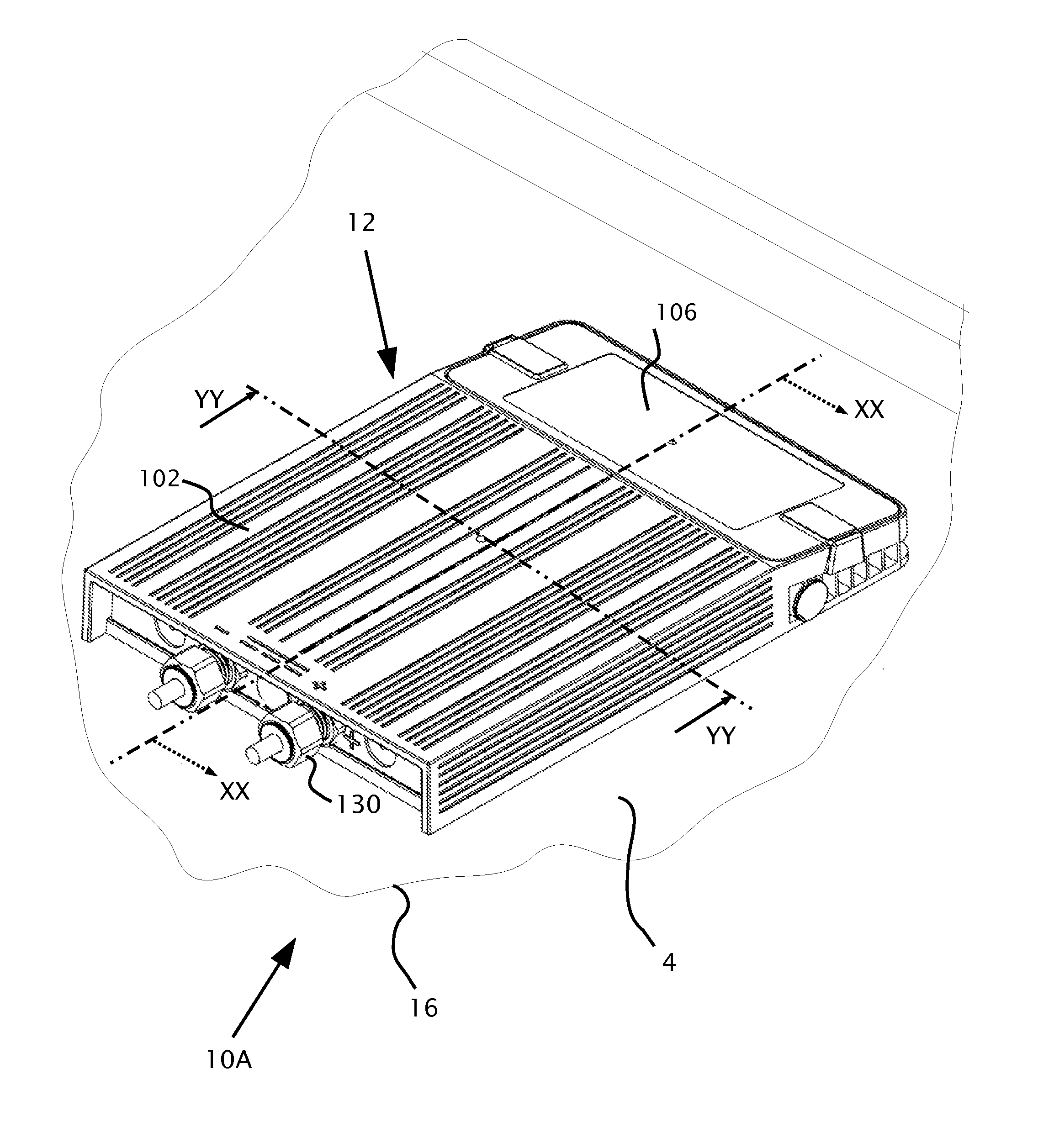
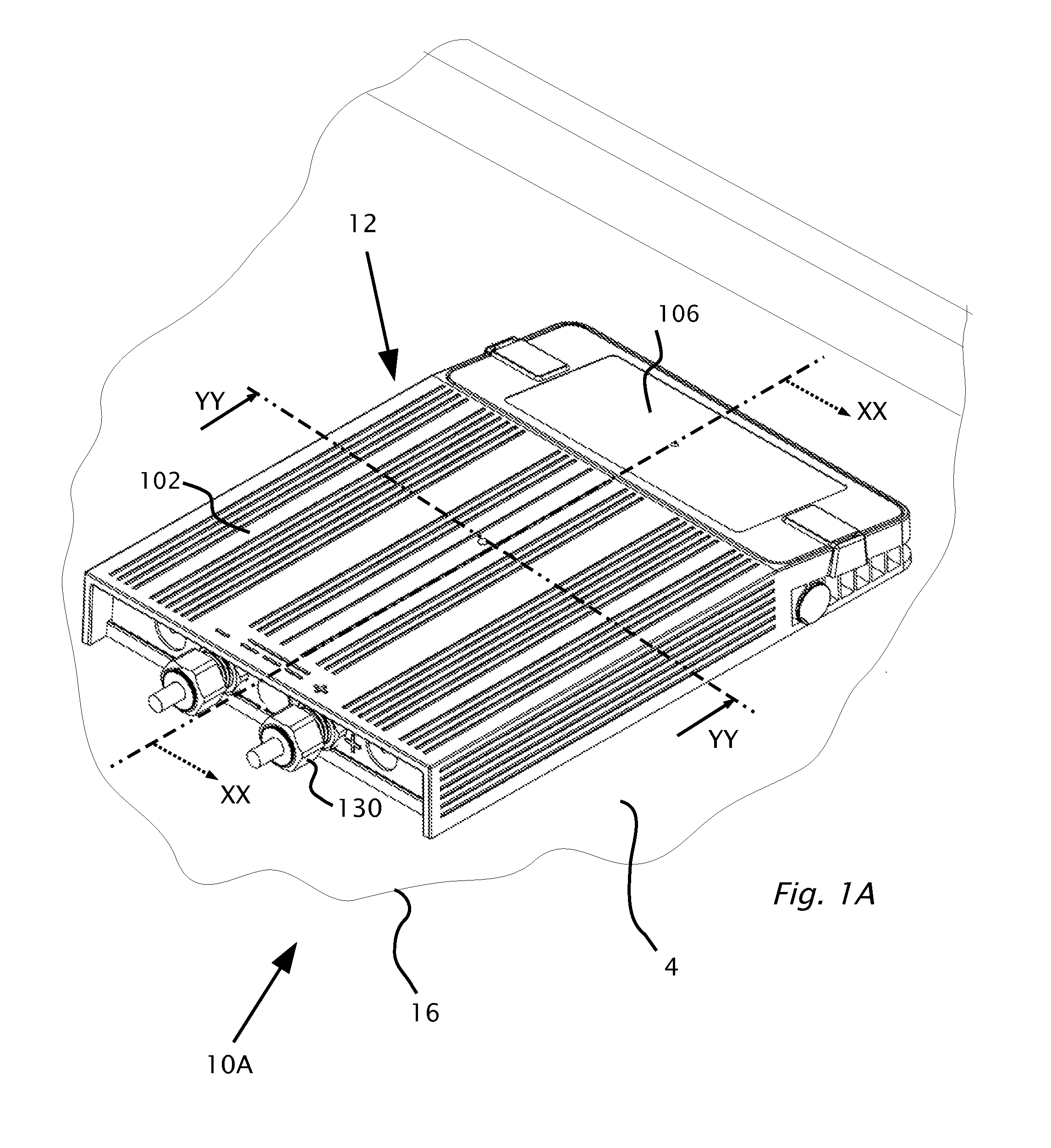
[0021]By way of introduction, diodes and / or electronic modules within junction boxes attached to the photovoltaic modules dissipate heat. When insulating junction boxes are used, heat must be dissipated mostly through air inside the junction box. When metallic junction boxes are used then heat may be dissipated directly through the junction box. However, the use of a metallic junction boxes may be inconvenient because of regulations which require accessible metallic surfaces to be grounded and extra wiring is required.

[0022]Before explaining exemplary embodiments of the invention in detail, it is to be understood that the invention is not limited in its application to the ...


PUM

PropertyMeasurementUnit
electricalaaaaaaaaaa
thermal conductionaaaaaaaaaa
electrical insulationaaaaaaaaaa

Abstract

A junction box used for making electrical connections to a photovoltaic panel. The junction box has two chambers including a first chamber and a second chamber and a wall common to and separating both chambers. The wall may be adapted to have an electrical connection therethrough. The two lids are adapted to seal respectively the two chambers. The two lids are on opposite sides of the junction box relative to the photovoltaic panel. The two lids may be attachable using different sealing processes to a different level of hermeticity. The first chamber may be adapted to receive a circuit board. The junction box may include supports for mounting a printed circuit board in the first chamber. The second chamber is configured for electrical connection to the photovoltaic panel. A metal heat sink may be bonded inside the first chamber. The first chamber is adapted to receive a circuit board for electrical power conversion, and the metal heat sink is adapted to dissipate heat generated by the circuit board.

Description

CROSS REFERENCE TO RELATED APPLICATIONS[0001]This application claims benefit from U.S. patent application 61 / 180,455 filed May 22, 2009, the disclosure of which is incorporated herein by reference.BACKGROUND[0002]1. Technical Field[0003]The present invention relates to a junction box for power sources, and specifically to a junction box for electrically connecting to a photovoltaic panel.[0004]2. Description of Related Art[0005]A photovoltaic module or photovoltaic panel is a packaged interconnected assembly of photovoltaic cells, also known as solar cells. Since a single photovoltaic module can only produce a limited amount of power, commercial installations include several modules or panels interconnected in serial and in parallel into a photovoltaic array. Electrical connections are made in series to achieve a desired output voltage and / or in parallel to provide a desired amount of current source capability. A photovoltaic installation typically includes the array of photovoltaic...

Claims


Application Information

Patent Timeline
Patent Type & Authority Applications(United States)
IPC IPC(8): H05K5/06H05K5/00
CPCG08B13/1409H02S40/345H02S40/34H05K5/02Y10T29/49117Y10S248/906Y02E10/50H05K5/062H05K7/2039H05K9/0009H05K9/0015H02G15/10H05K9/0007
Inventor SELLA, GUYHANDELSMAN, LIORSHMUKLER, VADIMADEST, MEIRGAZIT, MEIRGALIN, YOAV
Owner SOLAREDGE TECH LTD
Why Eureka
Try Eureka