Vapor barrier for flammable liquid storage tanks

a technology for flammable liquids and storage tanks, which is applied in the direction of transportation and packaging, mechanical equipment, and discharging methods of containers, etc., can solve the problems of igniting an explosive burning of vapor, loss of buoyancy, and use of plastics that are not intended for permanent repair

Active Publication Date: 2010-11-25
RIORDAN JOSEPH
View PDF17 Cites 22 Cited by
  • Summary
  • Abstract
  • Description
  • Claims
  • Application Information

AI Technical Summary

Benefits of technology

[0012]The vapor barrier for flammable liquid storage tanks provides a gas impermeable layer for covering the surface of a flammable liquid stored within a conventional flammable liquid storage tank. The vapor barrier further provides fire-suppression capabilities, and it should be understood that the vapor barrier may be applied to tankers, vessels, barges or any other type of container for flammable liquids. The vapor barrier prevents the build-up of flammable vapors over the flammable liquid surface. The vapor barrier is formed from a plurality

Problems solved by technology

If any flammable vapors are present during repair work on the cover, such as the repair of a pontoon of the cover, a spark from the welding may ignite an explosive burning of the vapor.
For example, one of the pontoons may sustain a relatively small opening through which liquid can seep resulting in a loss of buoyancy.
Use of the plastic is not intended as a permanent repair because the plastic may become impregnated with the flammable liquid.
Further, the plastic is disadvantageous because, at the conclusion of the service interval when reconditioning is mandatory, it is very difficult to remove the plastic so as to be able to clean the cover and make any permanent repairs.
Obviously, welding cannot be employed for repair until all liquid and liquid soaked flotation, such as the foamed plastic, has been removed.
However, the use of a plastic ho

Method used


Image

  • Vapor barrier for flammable liquid storage tanks
  • Vapor barrier for flammable liquid storage tanks
  • Vapor barrier for flammable liquid storage tanks

Examples


Embodiment Construction

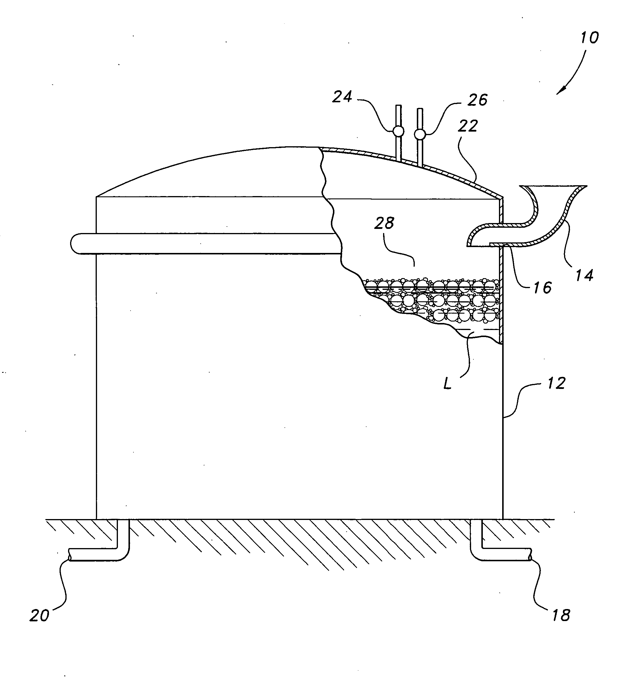
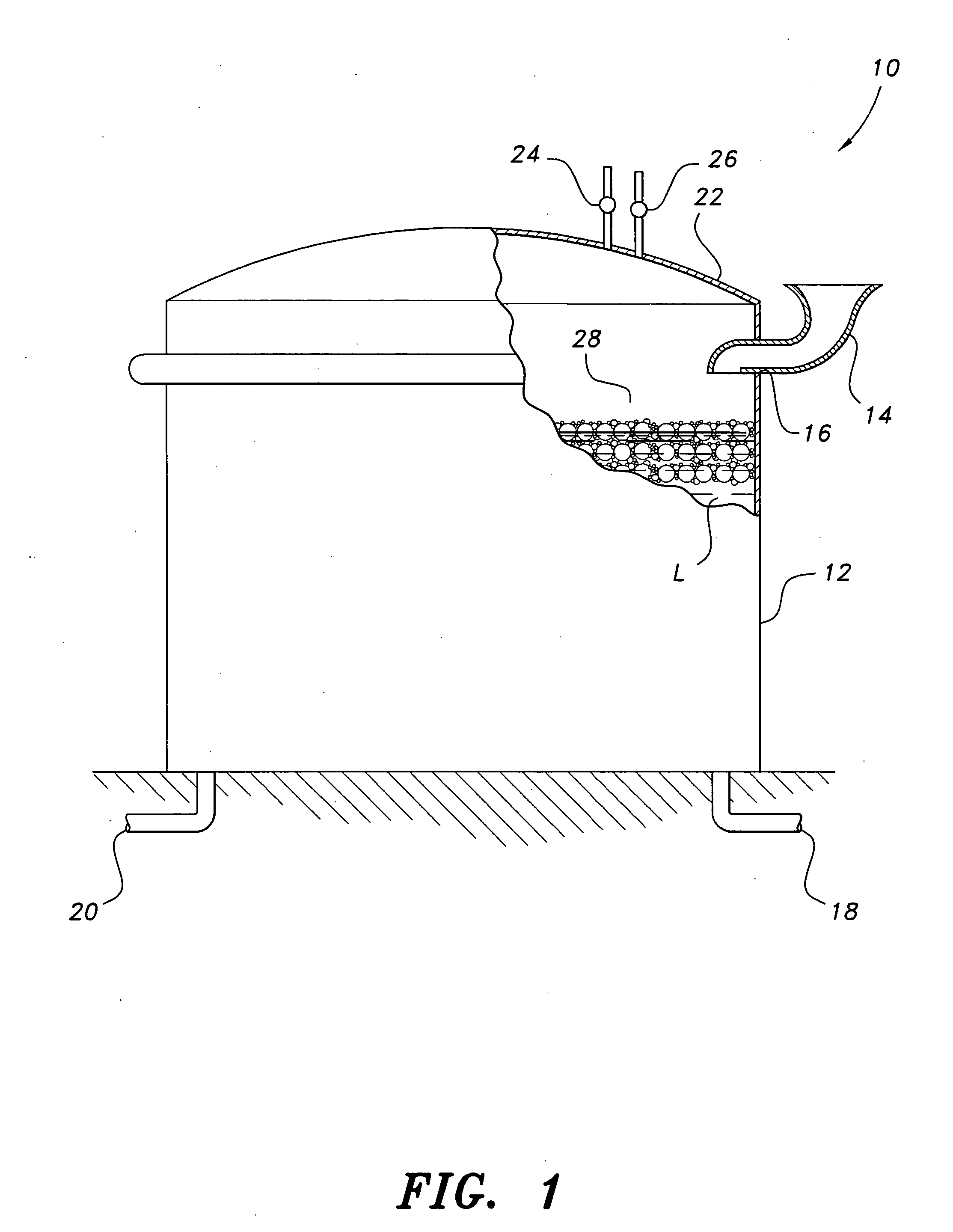
[0020]Referring to FIG. 1, an exemplary storage tank 10 has a vapor barrier for flammable liquid storage tanks deployed therein, the barrier being designated generally as 28. In addition to simply preventing the escape of vapor, the vapor barrier further provides fire suppression capabilities, and it should be understood that the vapor barrier may be applied to storage tankers, vessels, barges or any other type of container for flammable liquids. The liquid storage tank 10 is shown for exemplary purposes only and includes elements conventionally found in storage tanks for flammable liquids, such as oil, gasoline and the like. The housing 12 may be formed from steel or the like, as is conventionally known, and is either supported above the ground surface, or is at least partly buried in the ground. The tank is provided with a cover 22 and with pipes 18 and 20 for admitting flammable liquid L into the open interior region of housing 12, and for the withdrawal thereof when required. It...


PUM


Abstract

The vapor barrier for flammable liquid storage tanks provides a gas impermeable layer for covering the surface of a flammable liquid stored within a conventional flammable liquid storage tank, a tanker, a vessel or the like. The vapor barrier is formed from a plurality of spherical buoyant members. Each spherical buoyant member has a heat-resistant core or shell, a heat-reactive intumescent or flame retardant layer formed on an outer surface of the heat-resistant core, and an antistatic and oil-phobic layer formed on an outer surface of the heat-reactive intumescent layer. The vapor barrier may further be used with liquid storage tanks in which separation between the liquid and vapor phases is beneficial to prevent oxidation or other undesirable reactions.

Description

CROSS-REFERENCE TO RELATED APPLICATION[0001]This application claims the benefit of U.S. Provisional Patent Application Ser. No. 61 / 213,265, filed May 21, 2009.BACKGROUND OF THE INVENTION[0002]1. Field of the Invention[0003]The present invention relates to storage tanks for flammable liquids, and particularly to a vapor barrier for flammable liquid storage tanks that provides a vapor impermeable barrier layer with fire-suppressing capabilities for covering a surface of the flammable liquid.[0004]2. Description of the Related Art[0005]Flammable liquids, such as oil, gasoline and the like, must be stored in specialized storage tanks due to the flammable vapor that forms above the liquid surface. A common storage tank, often used in the petrochemical industry, is the “floating roof” tank. A typical floating roof tank is illustrated in FIG. 2. Tank 100 includes a hollow cylindrical housing 112 having an open upper end. The open upper end is sealed by a buoyant cover 114, having a circula...

Claims


Application Information

Patent Timeline
IPC IPC(8): B65D90/28B65D88/34B65D90/42
CPCB65D90/38
Inventor RIORDAN, JOSEPH
Owner RIORDAN JOSEPH
Why Eureka
Try Eureka