Aerodynamic component with a deformable outer shell

a technology of aerodynamic components and outer shells, applied in the direction of wing adjustment, wings, transportation and packaging, etc., can solve the problems of affecting the overall sound of the aircraft, the movable or pivotable flap, and the slot built in the outer contour between the movable or pivotable parts, and achieves small overall weight, good load resistance, and reduced local stresses

Inactive Publication Date: 2010-11-25
DEUTSCHES ZENTRUM FUER LUFT & RAUMFAHRT EV
View PDF18 Cites 15 Cited by
  • Summary
  • Abstract
  • Description
  • Claims
  • Application Information

AI Technical Summary

Benefits of technology

[0014]Another object of the present invention is to provide a reliable support of the outer shell of the aerodynamic component.
[0021]In another embodiment of the invention, the axis of rotation of the supporting element has an orientation parallel to the incoming airstream or parallel to the flight direction of the flying object or the aerodynamic component or transverse to the longitudinal axis of the aerodynamic component. For this embodiment, the supporting element is effective in a partial longitudinal region of the aerodynamic component. In case of a coaxial arrangement of the supporting element and the drive unit, the given extension of the aerodynamic component in the incoming flow is exploited for housing the supporting element and the drive unit. In case of the aerodynamic component or wing increasing in thickness from the between the leading or trailing edge, the increased distance between the upper and lower outer shell may be used for housing the drive unit.
[0026]In case of the supporting element or the outer surface of the same having only a small extension in the direction of the incoming airstream, the supporting element with its rotation only transfers local deformation forces to the outer shell. For another embodiment of the invention, the outer surface of the supporting element has an extension in the direction of the rotational axis such that the outer shell contacts the supporting element in the supporting region with an increased extension in this direction. In this way, the support between the supporting element and the outer shell in the direction of the incoming airstream or the airstream floating around the aerodynamic component may be improved.
[0030]The outer shell may be of any known type. According to one embodiment of the invention, the outer shell is constructed with an outer layer supported by inner stringers, in particular omega-stringers. Such design has proven to result in an outer shell with a good load resistance but a small overall weight. For this embodiment, the supporting region might be formed by a contact area between the stringers and the supporting element. A deformation force caused by the supporting element is transferred to the outer layer via the stringers, wherein the stringers guarantee a transfer of the deformation force in the increased contact surface between the stringer and the outer shell. This improved force transfer leads to decreased local stresses acting upon the outer layer.

Problems solved by technology

One disadvantage of movable or pivotable flaps involves slots built in the outer contour between the movable or pivotable parts.
As a disadvantage, the airflow streaming through a slot causes noise during the starting or landing process, which contributes a significant part of the overall noise caused by the flying object.
Another disadvantage of slots and edges is that in the neighborhood of the slots and edges, a laminar flow changes to a turbulent flow, which leads to a significant increase of the resistance along with increased fuel consumption and increased emissions of the flying object.

Method used


Image

  • Aerodynamic component with a deformable outer shell
  • Aerodynamic component with a deformable outer shell
  • Aerodynamic component with a deformable outer shell

Examples


Embodiment Construction

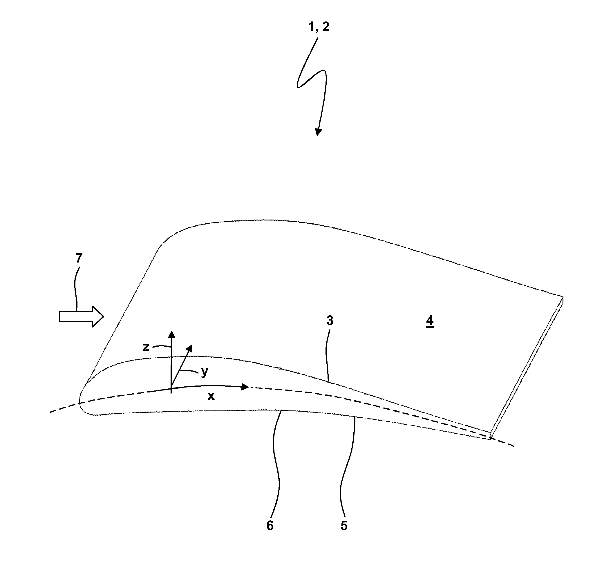
[0044]Referring now in greater detail to the drawings, FIG. 1 illustrates an aerodynamic component 1, here embodied as a wing 2 of a flying object or airplane. This example should not restrict the invention to this type of aerodynamic component. The invention may be used for changing the airflow around an aerodynamic component of any type by changing the contour of the aerodynamic component. To name only a few examples, the aerodynamic component might be a wing, a starting or landing flap, a pitch elevator, a yaw rudder, a fin or a vertical or horizontal tail and the like.

[0045]In the specification, the following system of axes is used for describing the orientations and geometries: The axis y is used for the longitudinal axis of the wing 2, whereas the axis x denotes a transverse axis along which the contour 3 of an upper surface 4 of the wing 2 as well as a contour 5 of a lower surface 6 of the wing 2 changes. A longitudinal plane is defined by the coordinates x, y. In case of the...


PUM


Abstract

The invention relates to an aerodynamic component, in particular a wing, a landing flap, a pitch elevator, a yaw rudder, a fin or tail. The aerodynamic component comprises an outer shell and at least one supporting element supporting said outer shell. A drive unit rotates the supporting element. A supporting region is created between the supporting element and the outer shell. The supporting region transfers deformation forces from the drive unit via the supporting element to the outer shell. The supporting element is designed and configured for changing the distance of the supporting region from a longitudinal plane of the aerodynamic component with a rotation of the supporting element. The outer shell comprises an elastic deformation region. The elastic deformation region is elastically deformed by the deformation forces with a rotation of the supporting element.

Description

CROSS REFERENCE TO RELATED APPLICATIONS[0001]This application claims priority to co-pending German Patent Application No. DE 10 2009 026 457.4 entitled “Aerodynamisches Bauteil mit verformbarer Auβenhaut”, filed May 25, 2009.FIELD OF THE INVENTION[0002]The present invention generally relates to an aerodynamic component for a flying object, in particular a wing, a starting or landing flap, a pitch elevator, a yaw rudder, a fin or a vertical or horizontal tail.BACKGROUND OF THE INVENTION[0003]In particular during the starting or landing process of a flying object, it is desired to influence the aerodynamic behavior of an aerodynamic component by changing the cross-section of the component or the contour of the outer shell of the component. It is known to lower a leading edge of a wing or flap during the landing or starting process in order to increase the ascending force or change the aerodynamic resistance. In general, this is done by using movable or pivotable front flaps or landing...

Claims


Application Information

Patent Timeline
Patent Type & Authority Applications(United States)
IPC IPC(8): B64C3/44
CPCB64C3/48
Inventor HEINTZE, OLAFMONNER, HANS PETERKINTSCHER, MARKUSRIEMENSCHNEIDER, JOHANNESLORKOWSKI, THOMAS
Owner DEUTSCHES ZENTRUM FUER LUFT & RAUMFAHRT EV
Why Eureka
Try Eureka