Connector of connecting light sensor and substrate and method of fabricating light sensor

a technology of connecting light sensor and substrate, applied in the field of connecting, can solve the problems of limited light sensor light reception direction, inability of light sensor to detect if an indicating object contacts the display panel, and inability to control the yield rate of the process

Inactive Publication Date: 2010-11-25
PIXART IMAGING INC
View PDF11 Cites 8 Cited by
  • Summary
  • Abstract
  • Description
  • Claims
  • Application Information

AI Technical Summary

Benefits of technology

[0009]The present invention further provides a method of fabricating a light sensor. The light sensor has a sensing unit and a lens. The sensing unit is utilized for receiving light so as to generate a light-sensing signal. The sensing unit has a transmission end for transmitting the light-sensing signal. The lens is utilized for focusing light on the sensing unit. The light sensor is applied in an optical touch system. The optical touch system has a substrate, a display panel, and a location-calculating circuit. The substrate is a glass. The display panel displays image through the substrate. The location-calculating circuit calculates a location of an indicating object on the display panel according to the light-sensing signal. The light sensor is contained in a connector. The connector rotates the light sensor so as to change a light-receiving direction of the light sensor to be parallel to the substrate, and the connector prevents the light sensor from high temperature fabrication. The method comprises filling an underfill between the sensing unit and a carrying component for fixing the sensing unit to the carrying component, attaching the lens on the sensing unit, and filling a fixing component around the sensing unit and the lens for packaging the sensing unit and the lens.

Problems solved by technology

However, when the light sensor is disposed on the substrate by means of the above-mentioned method, the light-receiving direction of the light sensor is limited.
In other words, when the light sensor is disposed on the glass substrate by the conventional package methods (TCP or COF), the light-receiving direction of the light sensor is vertical to the glass substrate, making the light sensor not able to detect if an indicating object contacts the display panel.
In the prior art, the FCB may be bended for rotating the light-receiving direction of the light sensor, but such process wastes time and the yield rate of the process is not easily controlled, increasing the cost of the optical touch system.

Method used


Image

  • Connector of connecting light sensor and substrate and method of fabricating light sensor
  • Connector of connecting light sensor and substrate and method of fabricating light sensor
  • Connector of connecting light sensor and substrate and method of fabricating light sensor

Examples


first embodiment

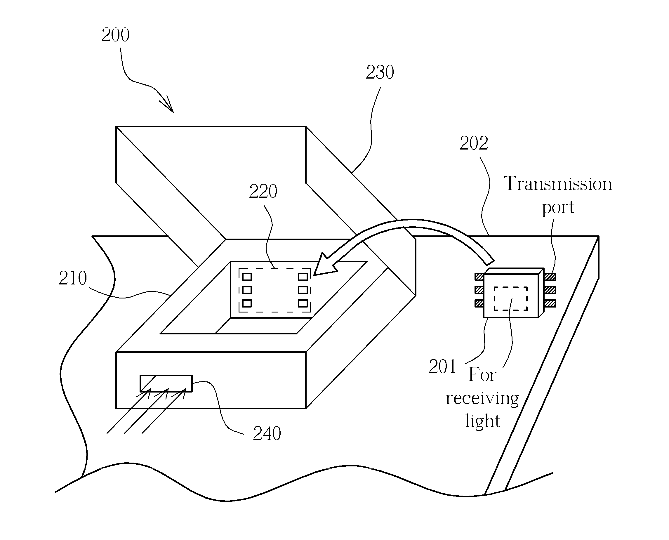
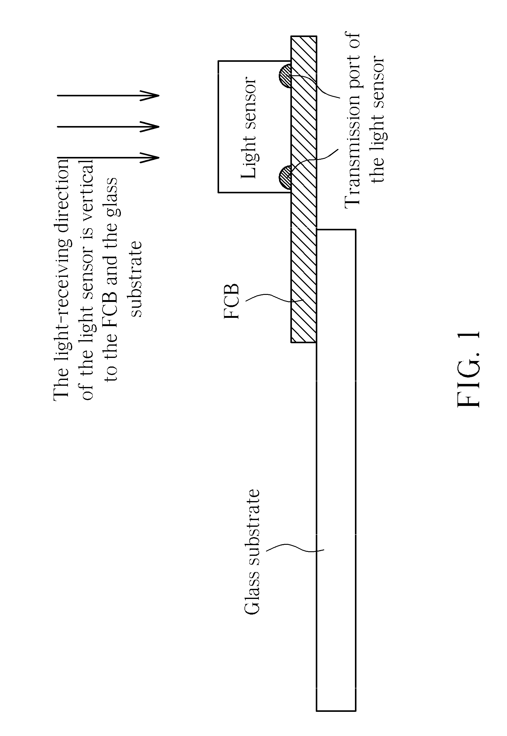
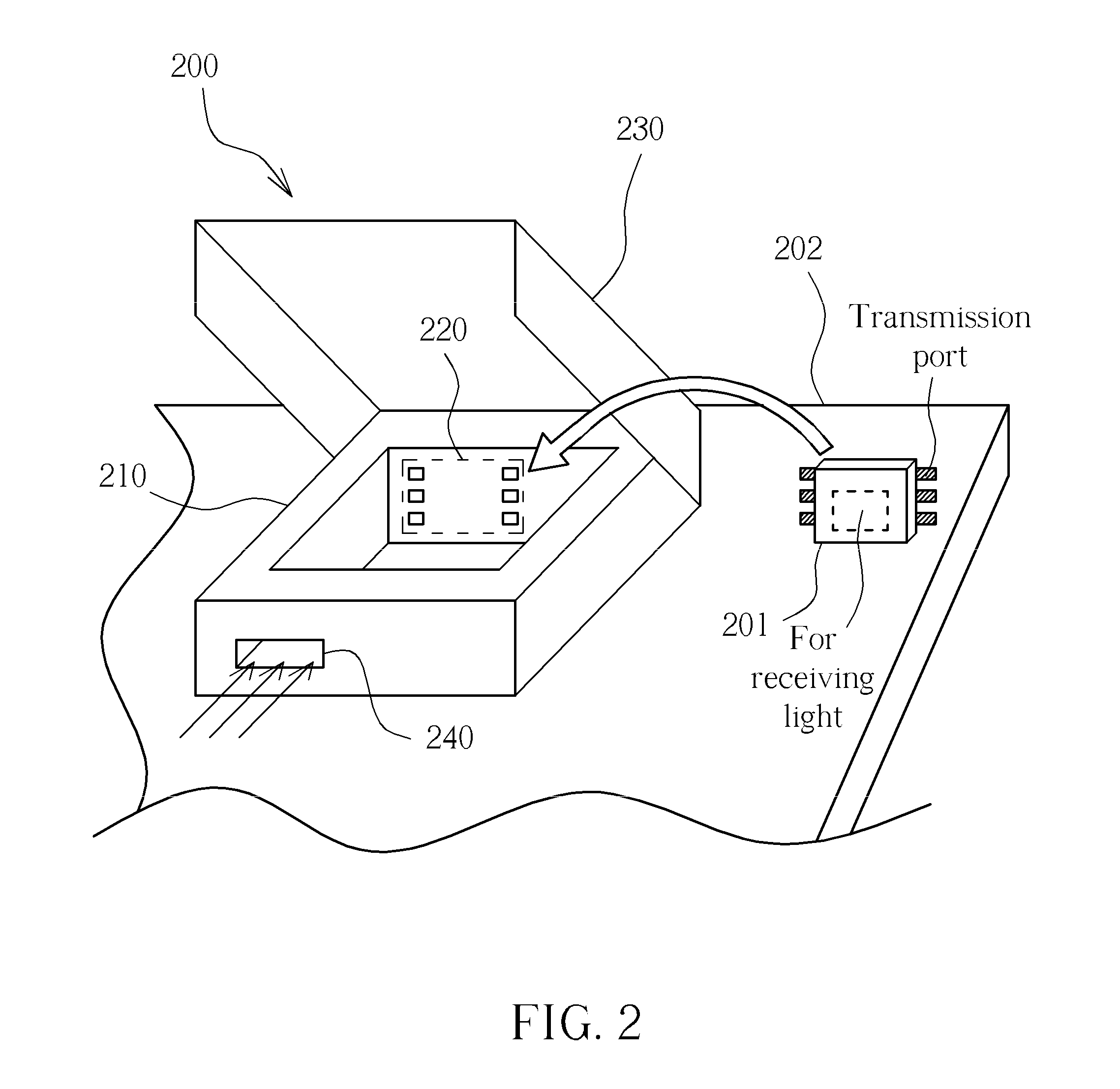
[0020]Please refer to FIG. 2. FIG. 2 is a diagram illustrating a connector 200 according to the present invention. In FIG. 2, the connector 200 is disposed on a substrate 202. The substrate 202 is a transparent substrate, e.g. a glass substrate or an ITO glass. The connector 200 comprises a body 210, a connecting port 220, a lid 230, and a light-receiving window 240. The body 210 has space large enough for containing a light sensor 201, and rotates the light sensor 201 so as to change the light-receiving direction to be parallel to the substrate 202. The connecting port 220 is contained in the body 210, and is coupled to the transmission port of the light sensor 201 so that the light sensor 201 is coupled to the substrate 202 through the transmission port of the light sensor 201 and the connecting port 220. The connecting port 220 may be realized by a plurality of L-shape golden fingers 221, as shown in FIG. 3 and FIG. 4. Each golden finger 221 comprises sections Li and L2. The sect...

second embodiment

[0021]Please refer to FIG. 5. FIG. 5 is a diagram illustrating a connector 500 according to the present invention. The operation principles and the structures of the connector 500, the light sensor 501, and the substrate 502 are respectively similar to those of the connector 200, the light sensor 201, and the substrate 202. Compared with the connector 200, the connector 500 further comprises a flexible printed circuit board (FPC) 550. The FPC 550 has a flexible-board connecting port 551. The flexible-board connecting port 551 of the FPC 550 is coupled between the connecting port 520 of the connector 500 and the substrate 502. Since, in the general fabrication of the flat display panel, the driving circuit of the display panel of is coupled to the substrate through an FPC, the fabrication of coupling the connector 500 to the substrate 502 through the FPC 550 only requires general fabrication facilities of the flat display panel.

[0022]Please refer to FIG. 6. FIG. 6 is a diagram illust...


PUM


Abstract

A connector of connecting a light sensor and a substrate is utilized for rotating the light sensor so that the light-receiving direction of the light sensor is parallel with the substrate. When the connector is utilized in an optical touch system, the light sensor can be disposed on the substrate of the optical touch system by means of general manufacturing facilities of flat display panels. Meanwhile, the light-receiving direction of the light sensor is parallel with the substrate of the optical touch system.

Description

CROSS REFERENCE TO RELATED APPLICATIONS[0001]This application claims the benefit of U.S. Provisional Application No. 61 / 180,890, filed on May 25, 2009.BACKGROUND OF THE INVENTION[0002]1. Field of the Invention[0003]The present invention is related to a connector, and more particularly, to a connector of connecting a light sensor.[0004]2. Description of the Prior Art[0005]The optical touch system comprises a display panel, a transparent substrate, a light sensor, and a location-calculating circuit. In general, the transparent substrate is a glass substrate. More particularly, the transparent substrate is an ITO (Tin-doped Indium Oxide) glass. The display panel displays images through the transparent substrate. The light sensor is a chip module disposed on the transparent substrate, and the light-receiving direction of the light sensor has to be parallel to the substrate for detecting if an indicating object (for example, a finger or a stylus) is on the transparent substrate, and acco...

Claims


Application Information

Patent Timeline
Patent Type & Authority Applications(United States)
IPC IPC(8): G06F3/042H01L31/0203H01R12/00H01L31/18
CPCG06F3/0428H01L31/0203H01L31/02325G01J1/0411G01J1/42G01J1/0295H01L2224/16225H01L2224/32225H01L2224/48091H01L2224/73204H01L2224/92125H01L2224/92247H01L2924/00011H01L2924/00014H01L2924/00H01L2224/0401
Inventor WANG, WEI-CHUNG
Owner PIXART IMAGING INC
Why Eureka
Try Eureka