Control device of power supply circuit

a power supply circuit and control device technology, applied in the direction of electric devices, safety/protection circuits, electric energy management, etc., can solve problems such as damage to smrs contacts

Active Publication Date: 2010-11-25
TOYOTA JIDOSHA KK
View PDF15 Cites 69 Cited by
  • Summary
  • Abstract
  • Description
  • Claims
  • Application Information

AI Technical Summary

Benefits of technology

[0049]According to this invention, the first relay and the third relay are provided in the conductive state, the charging rate of the capacitor that is an object of a precharge process is divided, and the capacitor is charged. At this point, if the first relay and the third relay of the power supply circuit being an object of abnormality detection are normal, within a time determined in advance, the voltage value of the load reaches a threshold value, and the charging rate of the capacitor reaches a threshold rate determined in advance. However, if within the time dete

Problems solved by technology

However, if the capacitor is charged directly by a battery, a lar

Method used


Image

  • Control device of power supply circuit
  • Control device of power supply circuit
  • Control device of power supply circuit

Examples


first embodiment

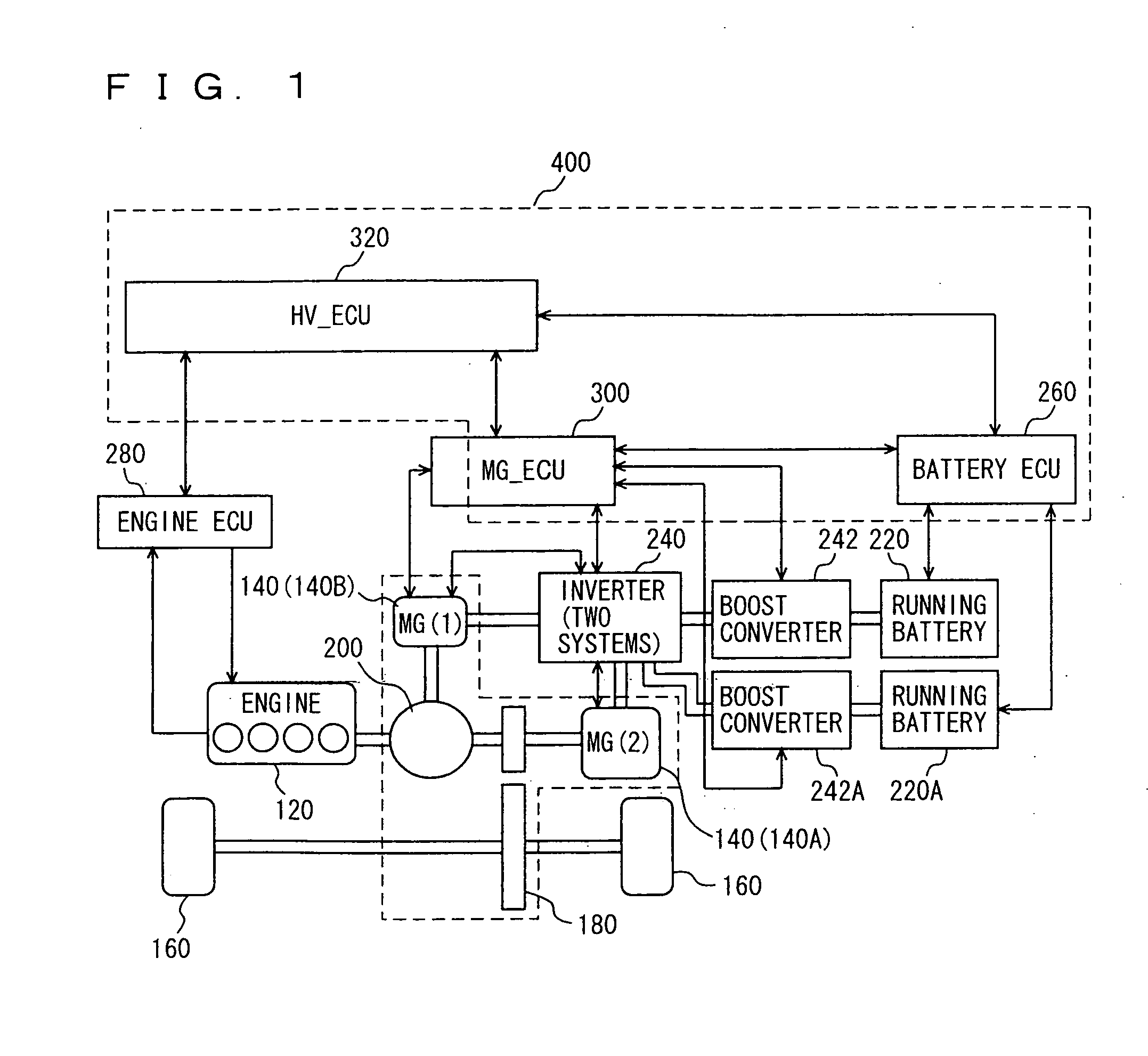
[0057]With reference to FIG. 1, a control block diagram of the whole hybrid vehicle including a control device in a first embodiment of the present invention is described. It should be noted that the present invention is not limited to a hybrid vehicle shown in FIG. 1. In the present invention, an internal combustion engine (hereinafter described as an “engine”), such as a gasoline engine, as a power source needs only to be a driving source (running source) for running a vehicle and a driving source of a generator. Further, a vehicle needs only to be one whose driving source is an engine and a motor generator and that can run by the power of the motor generator (regardless of whether the engine is stopped or not), and may be a hybrid vehicle that has another mode and on which a battery for running is mounted (not limited to hybrid vehicles of the so-called series type, parallel type and the like). Further, the present invention can be applied to an electric vehicle and a fuel cell v...

second embodiment

[0163]A second embodiment of the present invention will be described below.

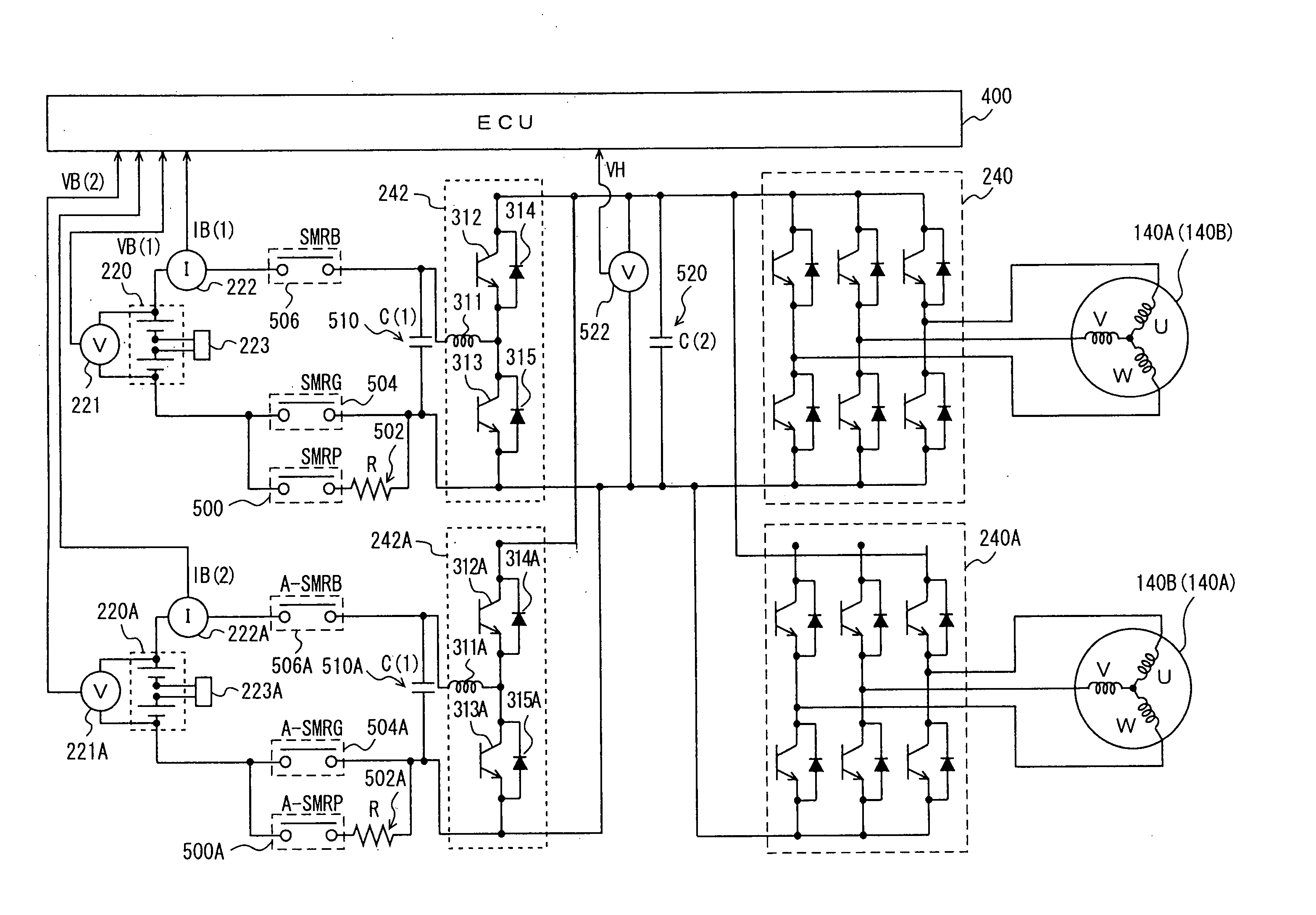
[0164]A control device of power supply circuits in the present embodiment performs failure determination (SMR immobility determination) of an electric circuit including SMRs for electrically connecting.a plurality of power supply systems (running batteries) and a load, in the same manner as in the first embodiment. In such a case of including a plurality of power supply systems (running batteries), if an immobility determination process in a single power supply system (running battery) is applied as in a conventional case, a path passing in another running battery may be formed because of the presence of a plurality of SMRs, leading to erroneous determination. It is therefore conceivable that the immobility determination in a single power supply system (running battery) is performed in series for each power supply circuit. In such a way, however, a configuration of common use of capacitor C(2) 520 on a high v...

third embodiment

[0200]In a control device in the present embodiment, the amount of electric power supply up to full charging and to such a level (a charging rate of 80%) that capacitor C(2) on the high voltage side is fully charged and a failure of a power supply circuit (fixation of an SMR) does not occur is divided in multiple stages (how much the amount of electric power supply is divided depends on the number of power supply circuits for which failure determination is performed), and the connection and disconnection of an SMRP for precharging of each power supply circuit is time-divided, thereby sequentially increasing the charging rate. Thus, failure determination of SMRPs of a plurality of power supply circuits can be performed by only one full charging of capacitor C(2) on the high voltage side without the need for discharging each time failure determination of SMRs of one power supply circuit is completed.

[0201]That is, a precharge process of S5020 to S5060 of FIG. 10 is performed using thr...


PUM


Abstract

An ECU executes a program including a step of turning on an SMRP and an A-SMRP if an ignition switch is turned on; a step of detecting voltage values VB(1) and VB(2) of running batteries when VH is detected and if VH is higher than 180 V; a step of detecting that SMRP connected to the running battery is welded, if VB(1) is higher than 150 V; and a step of detecting that A-SMRB connected to the running battery is welded, if VB(2) is higher than 150 V.

Description

TECHNICAL FIELD [0001]The present invention relates to a power supply circuit of a vehicle having a motor for running mounted thereon, such as an electric vehicle, a fuel cell vehicle or a hybrid vehicle, and more particularly to a technique to detect abnormality of a power supply circuit that connects and disconnects a power storage mechanism (storage batteries (batteries, secondary batteries), capacitors and the like) to a load.BACKGROUND ART [0002]A hybrid vehicle including a motor that operates with electric energy as well as an engine that operates with combustion energy as driving force sources of running of a vehicle has conventionally been known. This hybrid vehicle mainly includes the following types: (1) a series hybrid system in which an engine operates as a power supply source when the engine drives wheels without a motor; and (2) a parallel hybrid system in which wheels are driven by both an engine and a motor. Further, there is another type called a parallel-series hyb...

Claims


Application Information

Patent Timeline
IPC IPC(8): H02H7/16
CPCB60K6/445Y02T90/32B60L3/0053B60L11/123B60L11/14B60L11/1803B60L2210/14B60L2210/40B60L2270/20G01R31/3658H01M10/4264H01M10/44H01M10/441H01M10/46H01M10/482H01M2250/20H02J7/0031H02J7/1423H02J7/1438H02J7/1461H02J7/345Y02T10/6217Y02T10/6239Y02T10/7005Y02T10/7077Y02T90/34B60L3/04B60L2210/30B60L2240/545B60L2240/547B60L2240/549H02H7/00Y02T10/7241Y02T10/7225B60L3/0046G01R31/396B60L50/61B60L50/16B60L50/51B60L58/00Y02T10/62Y02T10/72Y02T10/7072Y02T90/40Y02T10/70Y02E60/50Y02E60/10B60W20/19H02J7/0049
Inventor ICHIKAWA, SHINJIOBAYASHI, KAZUYOSHI
Owner TOYOTA JIDOSHA KK
Why Eureka
Try Eureka