Vehicle light

a technology for vehicles and light sources, applied in the field of vehicle light, can solve the problems of deterioration, difficult adjustment of optical axes, pedestrians' inability to see the vehicle light, etc., and achieve the effect of suppressing the adverse effects of vibration on the vehicle light and reducing the load applied to the adjuster

Inactive Publication Date: 2010-11-25
STANLEY ELECTRIC CO LTD
View PDF6 Cites 10 Cited by
  • Summary
  • Abstract
  • Description
  • Claims
  • Application Information

AI Technical Summary

Benefits of technology

[0017]Furthermore, the stay can be positioned on or near a center of gravity of the vehicle light. Accordingly, when the optical axis of the vehicle light is adjusted by swinging the vehicle light by means of a known optical axis adju

Problems solved by technology

This means the visibility of the vehicle light by pedestrians may not be optimized and/or may deteriorate.
Even when they are assembled properly, there may be slight errors associated with the respective members, thereby accumulating with any assembly erro

Method used


Image

  • Vehicle light
  • Vehicle light
  • Vehicle light

Examples


Embodiment Construction

[0027]A description will now be made below to a vehicle light of the presently disclosed subject matter with reference to the accompanying drawings in accordance with exemplary embodiments.

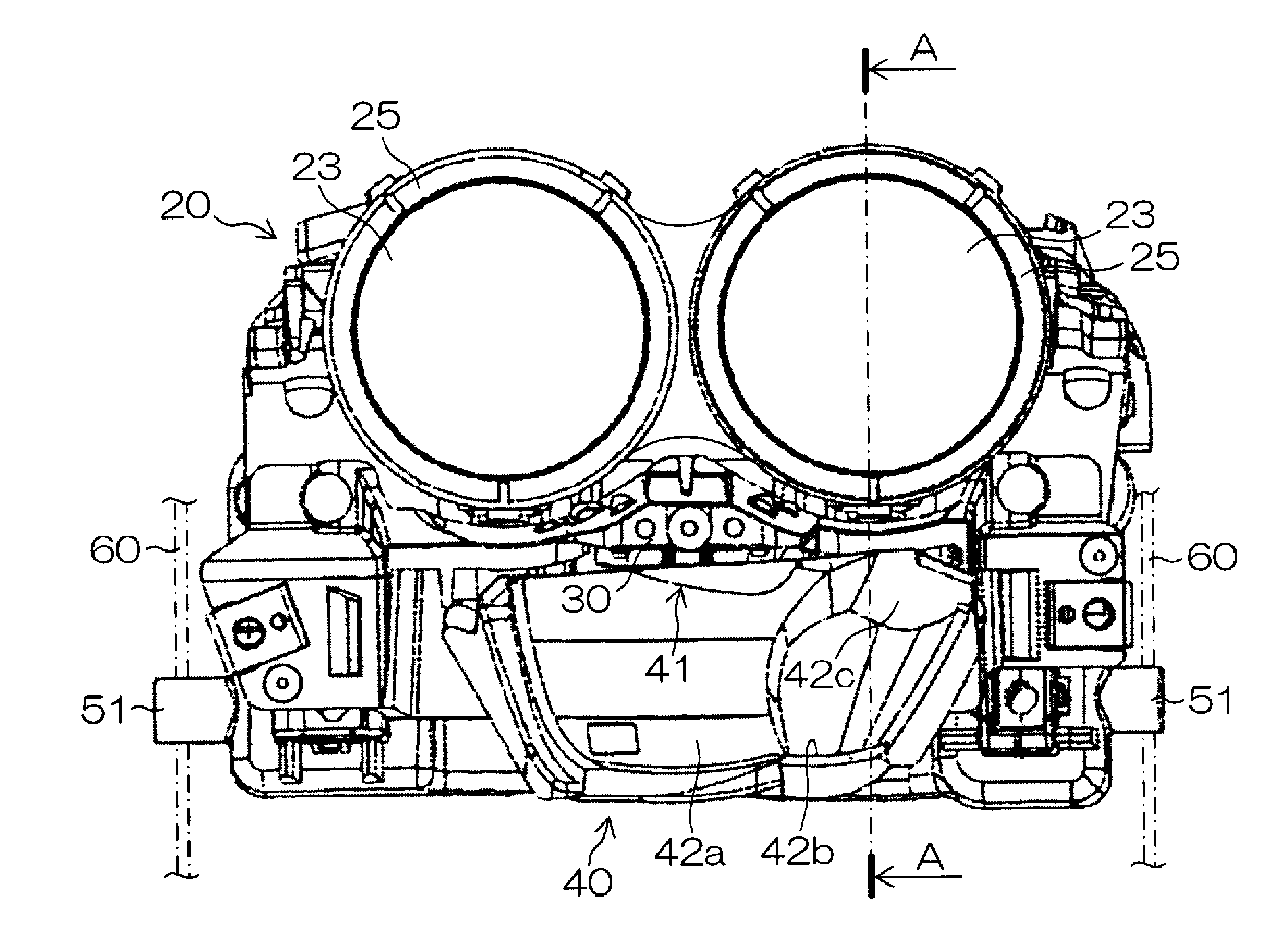
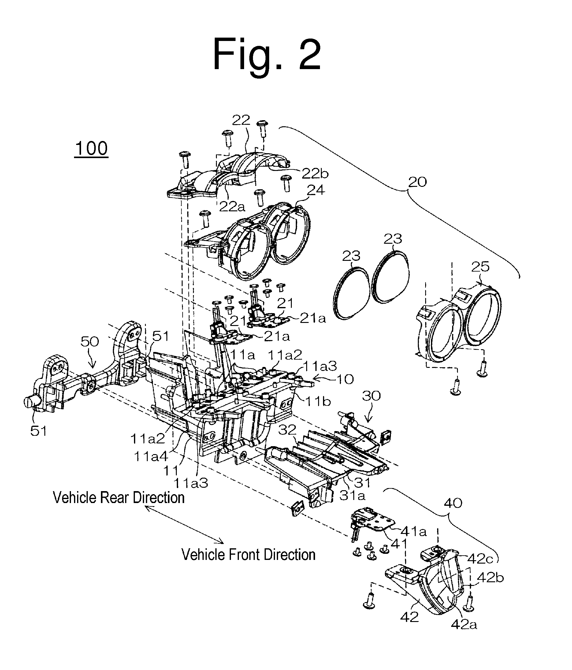
[0028]The vehicle light 100 of the present exemplary embodiment can be applied to a vehicle headlight, a fog light or the like for an automobile or other vehicle. As shown in FIG. 2, the vehicle light 100 can include a first heat sink 10, an upper optical system 20 (or first optical system), a second heat sink 30, a lower optical system 40 (or second optical system), and a stay 50, for example.

[0029]The first heat sink 10 can include a first heat sink body 11 disposed on the front side of a vehicle body, and a first heat radiation fin 12 disposed on the rear side of the vehicle body.

[0030]The upper optical system 20 can be a projection optical system configured to form a part of a desired light distribution pattern. As shown in FIGS. 2 and 3, the upper optical system 20 can be composed of a plural...


PUM


Abstract

A light can be configured by assembling an additional optical system in a lower optical system in a period of time that can be shorter than that of the conventional case. In addition to this, accumulation of assembly errors can be avoided during the assembling of these optical systems. The vehicle light can include a first optical system configured to form a part of a predetermined light distribution pattern, and a second optical system disposed adjacent to the first optical system and configured to form a part of the predetermined light distribution pattern. The second optical system can include a light source, and a reflector including a first reflecting surface, a second reflecting surface, and a third reflecting surface. The first reflecting surface can be disposed in the light emitting direction of the light source, and the first reflecting surface can reflect light emitted from the light source to a predefined illuminating direction, for forming a part of the predetermined light distribution pattern. The second reflecting surface can be disposed in the light emitting direction of the light source and extend from the lower end of the first reflecting surface, and can reflect light emitted from the light source towards the third reflecting surface. The third reflecting surface can be disposed at a position so that the light-emitting areas of the first optical system and the second optical system are observed as an integrated single light-emitting area of the optical systems, and can reflect light from the second reflecting surface to a predefined illuminating direction. The reflector can be integrally formed with the first reflecting surface, the second reflecting surface, and the third reflecting surface.

Description

[0001]This application is related to Applicant's co-pending U.S. patent application Ser. No. ______ attorney reference no. ST3001-0249 filed on the same date herewith, May, 24, 2010, and which disclosure is hereby incorporated in its entirety by reference.[0002]This application claims the priority benefit under 35 U.S.C. §119 of Japanese Patent Application No. 2009-124534 filed on May 22, 2009, which is hereby incorporated in its entirety by reference.TECHNICAL FIELD[0003]The presently disclosed subject matter relates to a vehicle light, and in particular, to a vehicle light including two types of optical systems adjacent to each other.BACKGROUND ART[0004]A conventional known vehicle light having two types of optical systems adjacent to each other is described in Japanese Patent Application Laid-Open No. 2007-305575, for example. The vehicle light can include an upper optical system and a lower optical system disposed below the upper optical system. In this vehicle light, the irradi...

Claims


Application Information

Patent Timeline
IPC IPC(8): F21S8/10F21W107/10
CPCB60Q1/0433B60Q1/068B60Q2200/36F21S48/1159F21S48/1388F21V29/75F21V15/01F21V29/004F21V29/2212F21Y2101/02F21S48/328F21V29/74F21Y2115/10F21S41/148F21S41/321F21S41/338F21S41/365F21S45/47
Inventor TOYOYAMA, HIDEKIAKIYAMA, YOSHIAKI
Owner STANLEY ELECTRIC CO LTD
Why Eureka
Try Eureka