Protocol for wireless networks

a wireless network and protocol technology, applied in the field of wireless networks, can solve the problems of increasing the complexity of the cable harness, increasing the cost of the car, and increasing the weight of the car, and achieves the effects of superior composability, flexibility, and simple implementation

Active Publication Date: 2010-11-25
ROBERT BOSCH GMBH
View PDF8 Cites 6 Cited by
  • Summary
  • Abstract
  • Description
  • Claims
  • Application Information

AI Technical Summary

Benefits of technology

[0017]Advantages of the present invention include simpler implementation, modular development, superior composability, and flexibility.

Problems solved by technology

In order to connect the peripherals, a large number of cables may be necessary, which increases the complexity of the cable harness, increases the weight of the car, and increases the costs of the car.
The increase in the number of cables may also lead to reliability problems in areas where the cable harness is mounted on moveable parts such as the side mirror, doors, seat, etc.
A problem associated with the architecture of FIG. 1 is that is that it has poor reliability.
For example, if one of the ECUs fails, then the entire associated subsystem is no longer able to operate.
Another problem is that there may be long time delays for end-to-end communication as gateways become bottlenecks.
Yet another problem is that modularity and scalability are limited by the underlying sub-network systems.
Although implementing at least some of the architecture of FIG. 1 wirelessly has been considered, wireless communication is unpredictable and hence raises questions about the responsiveness of such a system as compared to wired networks.
Another challenge is in operating the actuators in a given priority order.

Method used


Image

  • Protocol for wireless networks
  • Protocol for wireless networks
  • Protocol for wireless networks

Examples


Embodiment Construction

[0034]The embodiments hereinafter disclosed are not intended to be exhaustive or limit the invention to the precise forms disclosed in the following description. Rather the embodiments are chosen and described so that others skilled in the art may utilize its teachings.

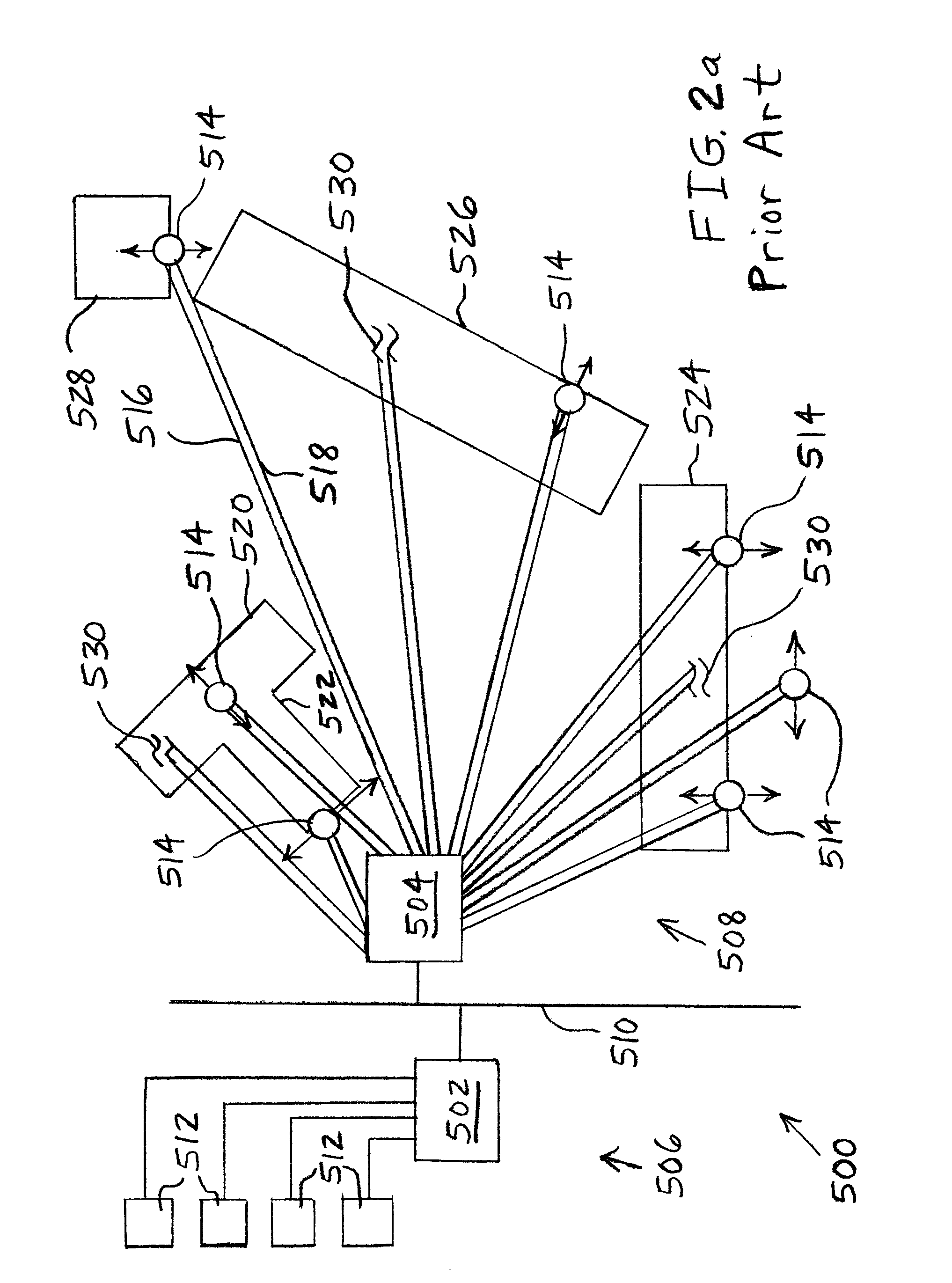
[0035]As described above with reference to FIG. 1, a wired automotive network may include several sub-networks connected together using a backbone network of ECUs and gateways. As shown in FIG. 2a, often several actuators are part of one sub-network and are controlled by a single ECU. The ECU may perform the command translation and send the appropriate signals to the desired actuators in a pre-defined order. The order may be decided according to the functional requirements. Due to practical limitations such as power control, only a set of actuators may be able to function at the same time.

[0036]FIG. 2a illustrates a known automotive body domain architecture 500 including central ECUs 502, 504 of a door module 506 and ...


PUM


Abstract

A wireless transmission method includes providing a commanding node and a plurality of sub-networks. Each of the sub-networks includes at least one responding node. Time slots are assigned to the sub-networks such that time slots assigned to each sub-network are interleaved in time with time slots assigned to at least one other sub-network. Within each time slot, at least one acknowledgement packet is transmitted from the at least one responding node before a command packet is sent from the commanding node within the time slot. Each at least one acknowledgement packet indicates whether or not a most recent command packet from the commanding node was correctly received by the responding node.

Description

BACKGROUND[0001]1. Field of the Invention[0002]The present invention relates to wireless networks, and, more particularly, to protocols for wireless networks.[0003]2. Description of the Related Art[0004]Typically, automotive body domain applications such as seat control, window lift, mirror adjustment, and light control are distributed over the entire car and are interconnected via field bus communication systems. Current architectures have grown fast over the last decades as more and more convenience functions are introduced to the automotive industry.[0005]The current architectures are hierarchical architectures in which several electronic control units (ECUs) are located near the body domain applications such as the seat ECU under the seat, the door ECU within the door, the ECU for rear light control in the trunk of the car, etc. All these ECUs are interconnected over field bus systems such as the “controller area network” (CAN) field bus, and these ECUs form the first hierarchy ...

Claims


Application Information

Patent Timeline
Patent Type & Authority Applications(United States)
IPC IPC(8): H04J3/00
CPCH04L1/1854H04L12/4035H04L12/44H04L12/4625H04W84/12H04L2012/40273H04W28/04H04W28/16H04L2001/0092
Inventor JAIN, VIVEKHOGENMUELLER, THOMAS
Owner ROBERT BOSCH GMBH
Why Eureka
Try Eureka