Module structure and plant construction method

a technology of modular structure and plant, applied in the direction of nuclear power plants, building repairs, nuclear engineering, etc., can solve the problems of affecting the construction process, and unable to ensure the space for temporal placement, so as to facilitate the adjustment of position, and shorten the construction period

Inactive Publication Date: 2010-12-02
HITACHI LTD
View PDF10 Cites 18 Cited by
  • Summary
  • Abstract
  • Description
  • Claims
  • Application Information

AI Technical Summary

Benefits of technology

[0024]The module structure of the present invention includes the support member which temporarily supports the facility device component at the designed position and which constitutes the scaffolding for attaching the facility device component and forming the cell and the box-shaped frame which is possible to be carried into the inner space of the cell while fixing the support member, and then, the support member and the frame are temporarily assembled with the detachably attachable joint means. Accordingly, in the case that the conclusive operational mounting is not planned, namely, in the case that a pipe is to be attached in the air of the cell, the construction operation of the wall face and the ceiling face of the cell can be performed in parallel to attaching of the facilit

Problems solved by technology

(1) Since the operational scaffolding 5 for concrete wall casting for constructing a wall face 3 of the cell 1 remains therein, opening space of the ceiling face becomes small. Accordingly, the operational scaffolding 5 for concrete wall casting and facility device component 4 hung by the large crane are mutually interfered and the amount to be carried into the cell 1 is restricted. Further, since the amount of carrying-in for one time is restricted, there may be a case that carrying-in operation with the large crane has to be performed plural times.
(2) As illustrated in FIG. 10B, in the case that the facility device component 4 is attached to a vicinity of the wall face 3, the attaching operation has to be performed after moving the previously arranged operational scaffolding 5 for concrete wall casting. Accordingly, moving operation of the operational scaffolding is often required. There may be a case that moving operation of such scaffolding accompanies disassembling and assembling. In this case, the construction process is interrupted.
(3) When carrying-in is performed with a large crane, the facility device component 4 is

Method used


Image

  • Module structure and plant construction method
  • Module structure and plant construction method
  • Module structure and plant construction method

Examples


Embodiment Construction

[0046]In the following, embodiments of the present invention will be described with reference to the drawings.

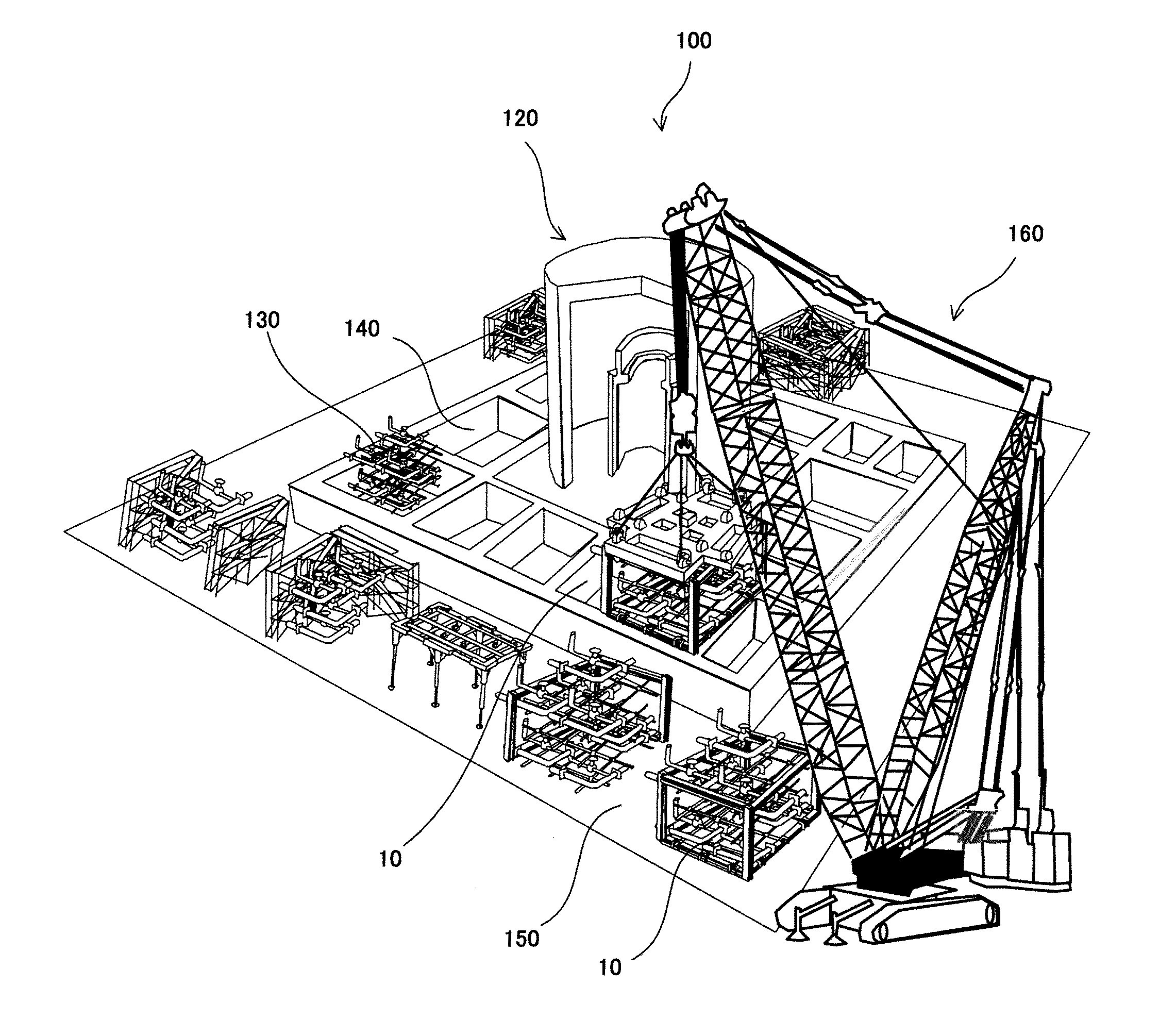
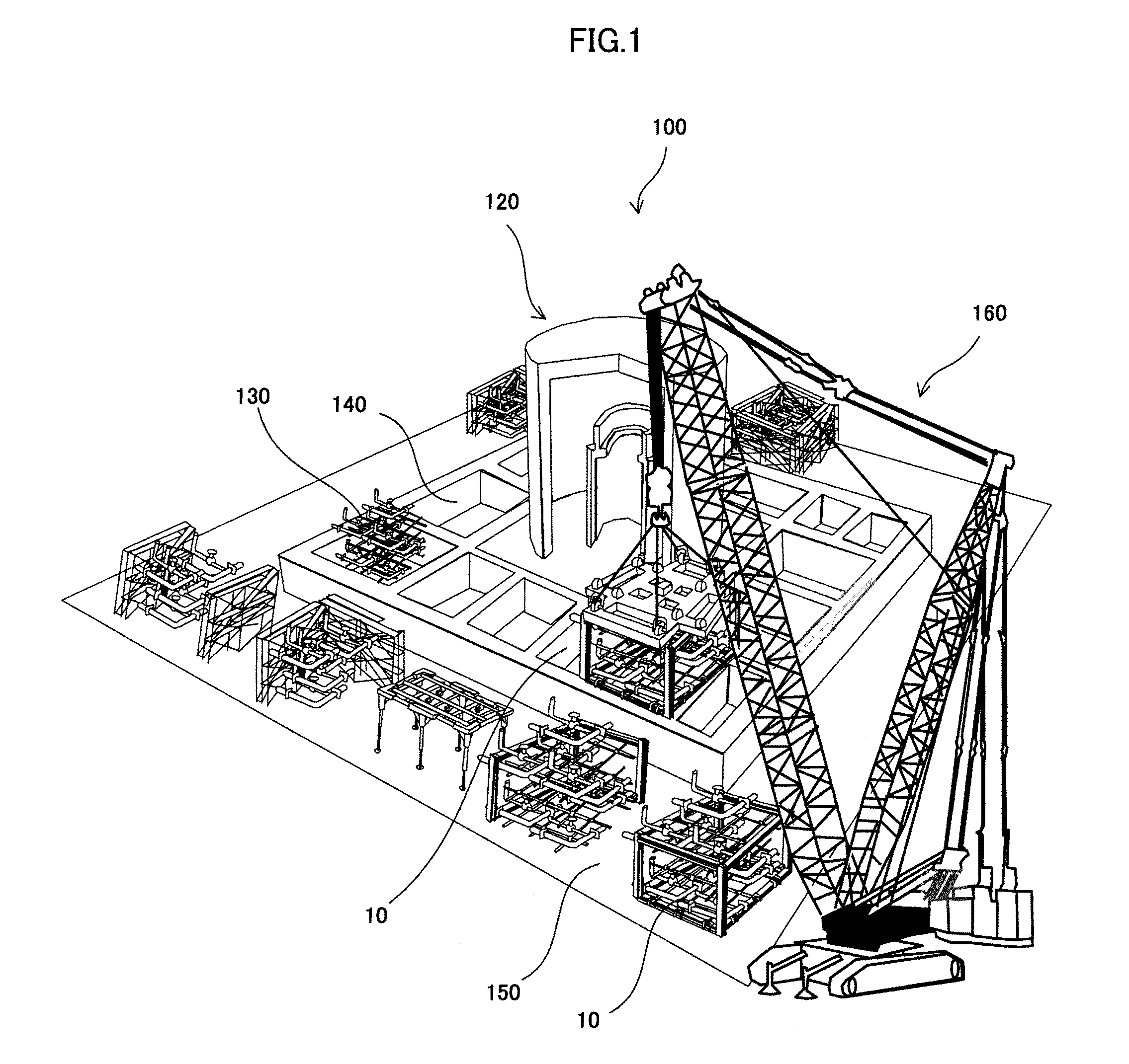
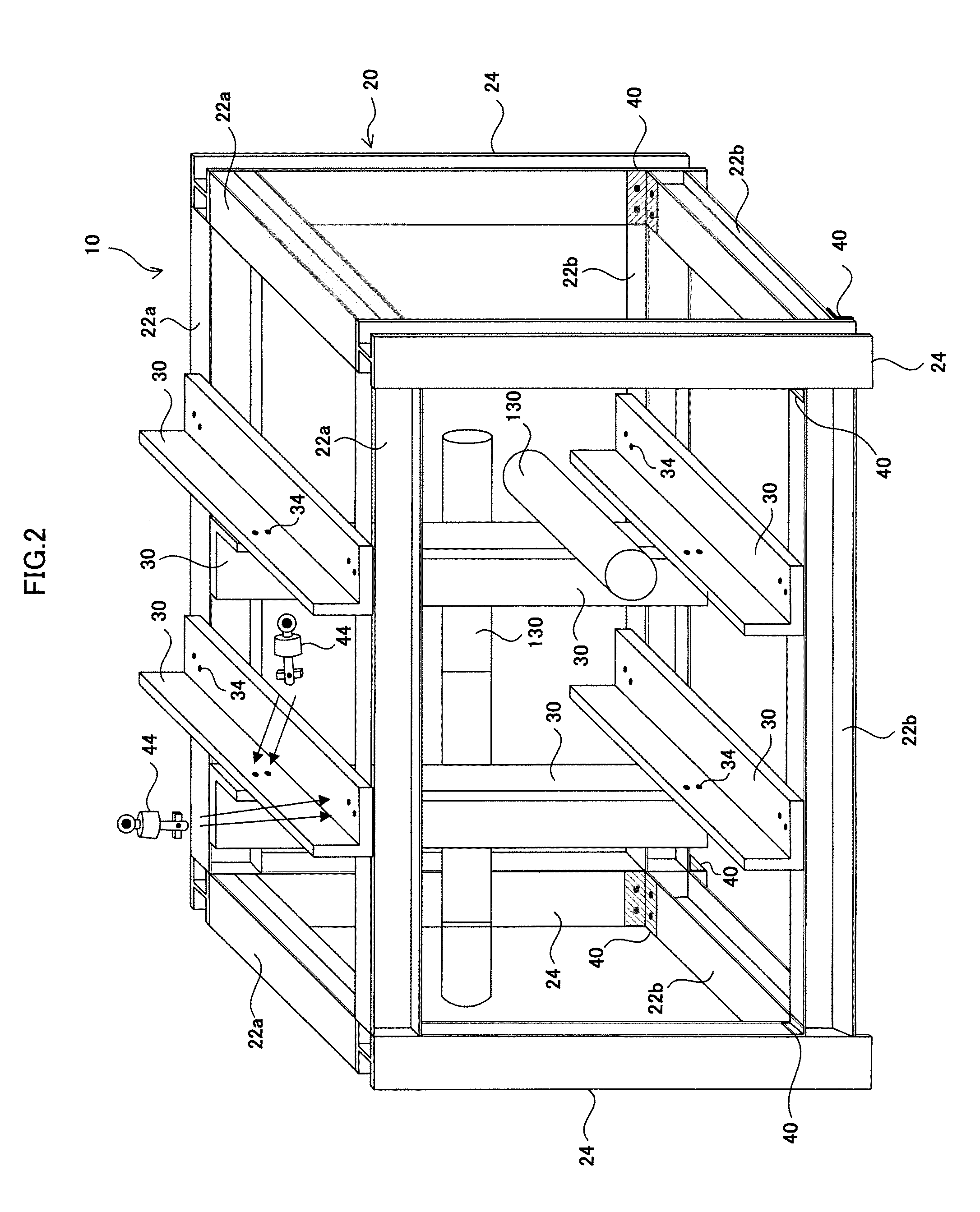
[0047]FIG. 1 is an explanatory view of plant facilities. FIG. 2 is an explanatory view of a module structure according to an embodiment of the present invention.

[0048]As illustrated in FIG. 1, following description is performed on a nuclear power generation plant as an example of a plant to which the module structure of the present invention is applied. A nuclear power generation plant 100 is constituted with a number of facility devices in addition to a nuclear reactor pressure vessel 120 at a center part. Cells 140 which are plurally divided for each facility device and the like are formed around the nuclear reactor pressure vessel 120. A variety of facility devices and a number of pipes (i.e., facility device components 130) are attached to the cells 140.

[0049]A module structure 10 of the present invention is formed to be a box shape capable of being carried into inner sp...


PUM


Abstract

The present invention provides a module structure and a plant construction method capable of easily attaching a facility device of a plant and shortening a plant construction period. The module structure of the present invention includes a support member which temporarily supports a facility device component to be arranged in a cell constituting a plant at a designed position and which constitutes scaffolding for attaching the facility device component and forming the cell, a box-shaped frame which is possible to be carried into inner space of the cell while fixing the support member, and joint means which is detachably attachable and which temporarily assembles the support member and the frame.

Description

BACKGROUND[0001](a) Field of the Invention[0002]The present invention relates to a module structure and a plant construction method, and in particular, relates to a module structure and a plant construction method suitable for plant construction of nuclear power generation and the like.[0003](b) Description of the Related Art[0004]A plant such as a nuclear power generation plant is a building of reinforced concrete structure and is divided into a plurality of cells for each facility device and the like. A plant construction method in the related art is roughly classified into a process to form a plurality of cells prepared by arbitrarily dividing a plant building for each attaching and the like of the facility device and a process to attach pipes and facility devices to be attached in each formed cell.[0005]FIGS. 10A and 10B are explanatory views of a plant construction method in the related art. As illustrated in FIG. 10A, in a cell 1 which is prepared by dividing a plant building,...

Claims


Application Information

Patent Timeline
IPC IPC(8): E04H5/02E04H1/00E04B1/00
CPCG21D1/00E04G21/14
Inventor IMAOKA, SHIZUOEBATA, SHINICHIWADA, MASAOMIFUKUSHIMA, SHIGERUYOSHIZAKI, MASATOSHISATOU, NOBUHARU
Owner HITACHI LTD
Why Eureka
Try Eureka