Method and flow sleeve profile reduction to extend combustor liner life

a technology of flow sleeve and profile reduction, which is applied in the direction of machines/engines, mechanical equipment, light and heating equipment, etc., can solve the problems of non-uniform thermal loading of the liner

Inactive Publication Date: 2010-12-02
GENERAL ELECTRIC CO
View PDF18 Cites 6 Cited by
  • Summary
  • Abstract
  • Description
  • Claims
  • Application Information

AI Technical Summary

Problems solved by technology

These DLN combustors often run with different fuel splits going to var

Method used


Image

  • Method and flow sleeve profile reduction to extend combustor liner life
  • Method and flow sleeve profile reduction to extend combustor liner life
  • Method and flow sleeve profile reduction to extend combustor liner life

Examples


Embodiment Construction

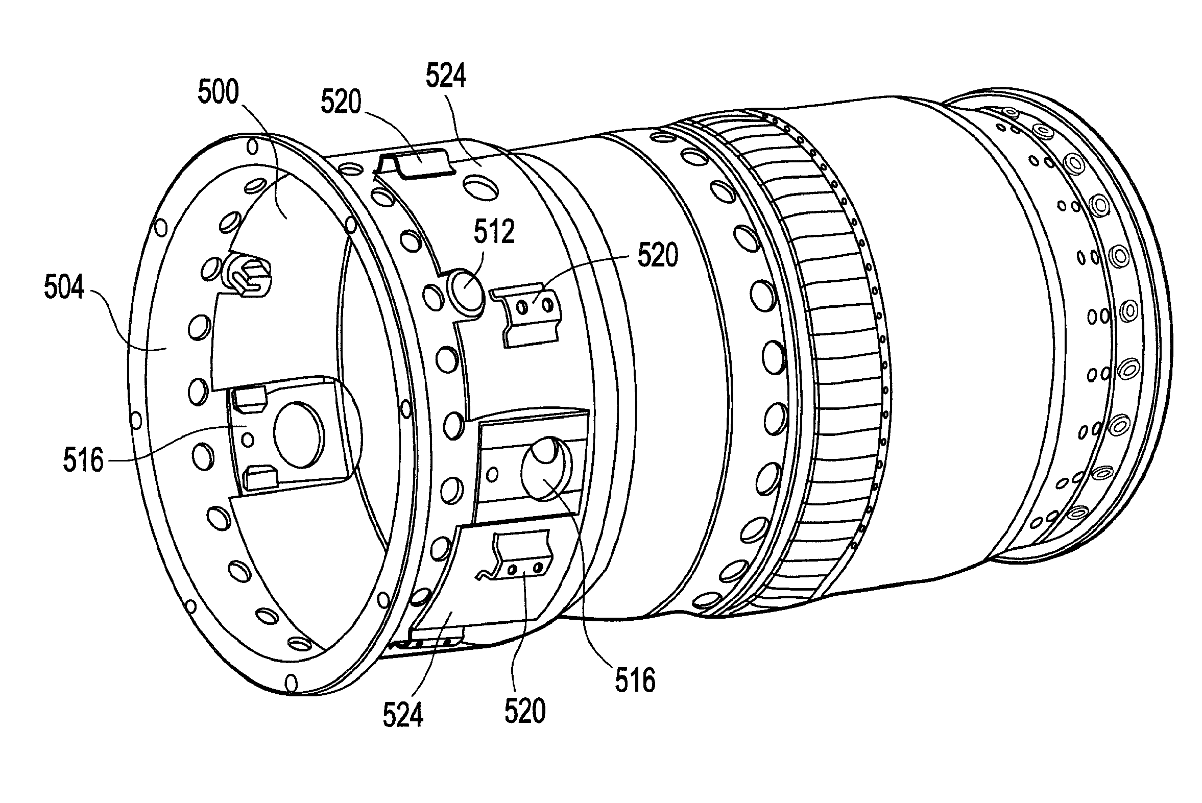
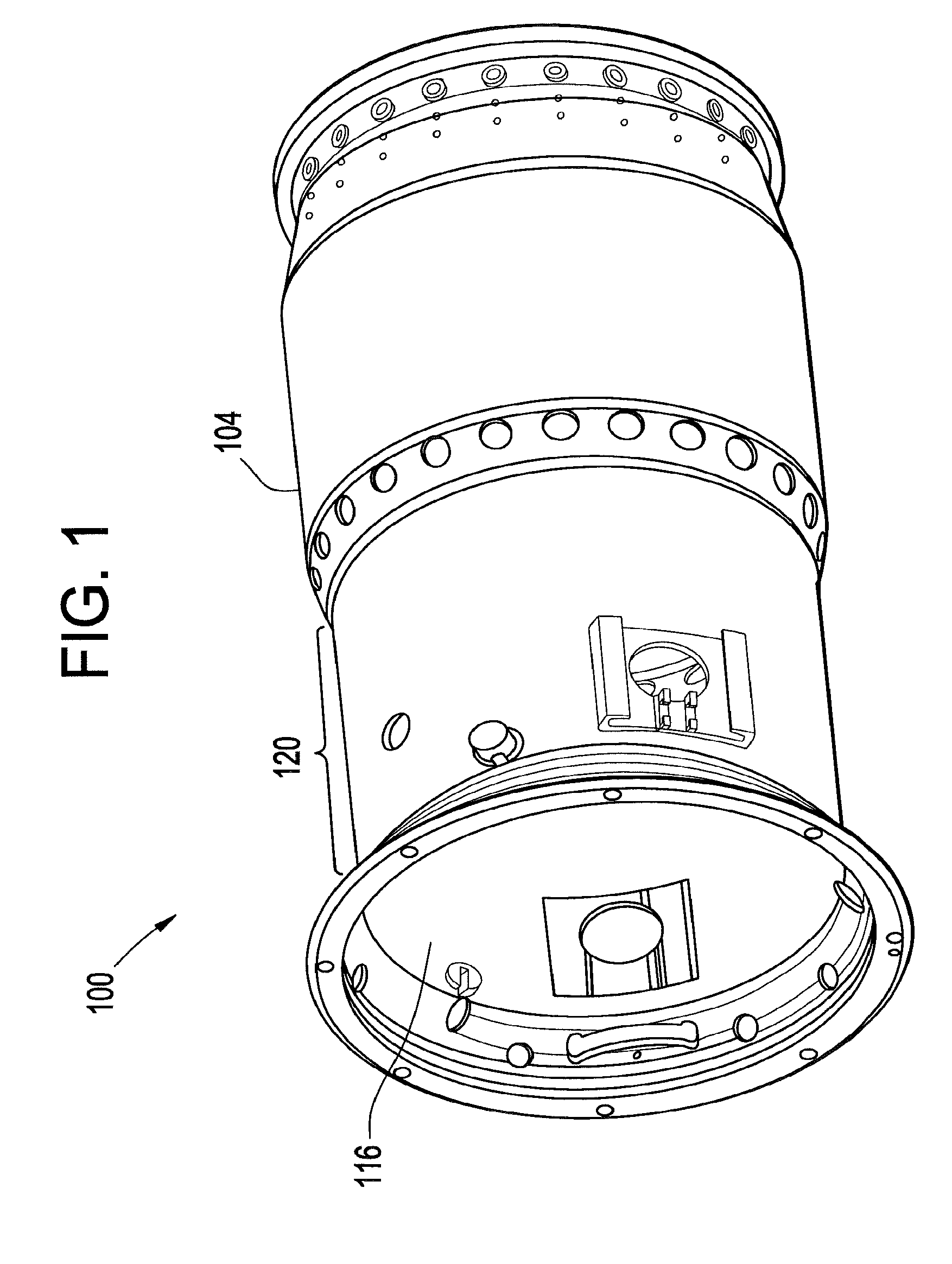
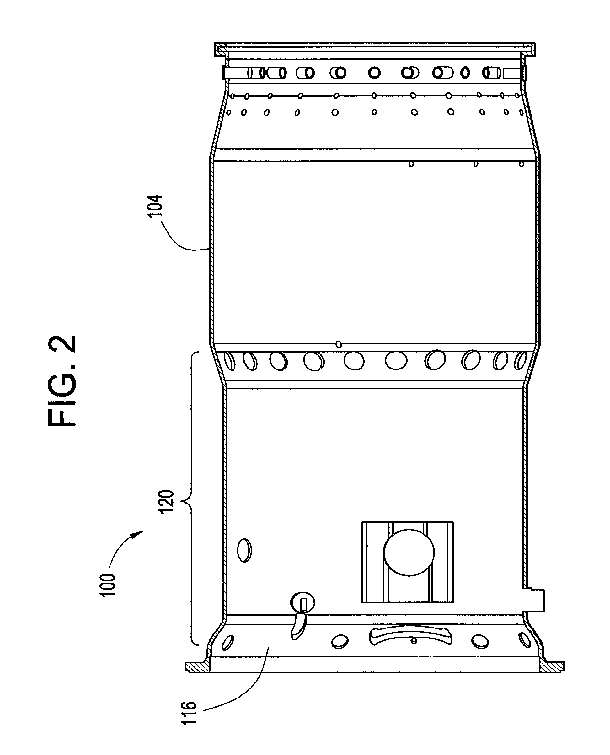
[0019]In FIGS. 1-3, a flow sleeve 100 according to an embodiment of the invention is generally circular in cross section, although other shapes are possible. The length dimension of the flow sleeve 100 in FIGS. 1-3 (i.e., left to right in FIGS. 1-3) may be considered the axial dimension of the flow sleeve 100, while the “profile” of the flow sleeve 100 may be considered the shape of the flow sleeve 100 as seen by viewing an outer surface 104 (and, thus, an inner surface) of the flow sleeve 100 taken along this axial dimension. The flow sleeve 100 may be part of a diffusion or DLN type (or other type) of combustor of a gas turbine that utilizes film cooling. As such, the flow sleeve 100 may at least partially surround or be concentric with at least a portion of a liner 108 (FIG. 3) that is also part of the combustor.

[0020]As mentioned, the liner 108 is typically exposed to relatively high temperatures resulting from combustion of the air and fuel mixture within the liner 108. Thus, a...


PUM


Abstract

A gas turbine includes a combustor liner having at least one hole formed therein. The gas turbine also includes a flow sleeve that at least partially surrounds the liner thereby forming a plenum between the flow sleeve and the liner, the plenum having an airflow therethrough, a portion of the airflow passing through the at least one hole in the liner and into the liner thereby reducing the mass of the airflow in the plenum. The flow sleeve has an axial profile that is reduced in cross section dimension at a predetermined axial location of the flow sleeve, thereby reducing a width of the plenum at the predetermined axial location. The reduction at the cross section dimension in the flow sleeve increases a velocity of the airflow in the plenum at the predetermined axial location, the increased velocity airflow increasing transfer of heat away from the liner.

Description

BACKGROUND OF THE INVENTION[0001]The subject matter disclosed herein relates to gas turbines and, in particular, to the profile of a flow sleeve that extends the useful life of a liner of a gas turbine combustor.[0002]In a gas turbine that includes a diffusion type (i.e., non-premixed) combustor, relatively high head end temperatures may be experienced on the inner surface of, e.g., the film-cooled, multi-nozzle quiet combustor (“MNQC”) liner (for example, near the row #1 mixing holes). In general, the “head end” of the combustor typically refers to the portion or area of the combustor (usually at one end thereof) where the fuel and air are premixed together for subsequent combustion further along within the combustor. The relatively high head end temperatures may be increased even further when the combustor burns certain fuels, such as syn gas fuels (e.g., LHV, CO and H2 in fuel composition, flowing through primary and secondary fuel passageways). To mitigate this issue, performanc...

Claims


Application Information

Patent Timeline
IPC IPC(8): F02C7/12F23R3/42
CPCF23R3/005F23R3/002
Inventor BARTON, JESSE ELLISBERRY, JONATHAN DWIGHTBROWN, JAMES THOMASHADLEY, MARK ALLANMELTON, PATRICK BENEDICTYAKUBOVA, SVETLANA
Owner GENERAL ELECTRIC CO
Why Eureka
Try Eureka