Watercraft Immobilizing System

a technology for immobilizing systems and watercraft, which is applied in the field of watercraft immobilizing systems, can solve the problems of high efficiency and difficult deterrence of high-speed conventional watercraft, and achieve the effects of improving stability and facilitating, rapid and remote deployment and recovery

Inactive Publication Date: 2010-12-02
GAYTON RICHARD J A
View PDF31 Cites 15 Cited by
  • Summary
  • Abstract
  • Description
  • Claims
  • Application Information

AI Technical Summary

Benefits of technology

[0015]This subject invention features five banks of storage rollers, featuring multiple removable line cartridges, that in the preferred embodiment may be easily, rapidly and remotely deployed and recovered by means of electric motors. Each bank features secondary winches at the extremities, which can also be operated remotely by electric motor. These winches store the wire that deploys the weighted submersible dual rollers system for each bank. The weighted dual rollers are designed to place the towed array below the surface immediately adjacent to the various storage cartridges. These rollers may be further prevented from riding up above the water surface by utilization of preventer wires that are led from the roller extremities to a strong point on deck forward of the roller installation. The main bank is mounted off the vessel's transom. Two transom outriggers, one at each extremity, are designed to deploy a second and third bank of storage rollers also featuring multiple removable line cartridges. The weighted submersible dual rollers in the way of these aft outriggers are designed to be connected to the extremities of the weighted submersible dual rollers of the main transom bank, effectively forming one rigid unit. Deep fins are situated at the outer

Problems solved by technology

Such attackers have proven that the use of high speed conventionally powered watercraft is highly effective and very difficult to deter.
The current deterrents

Method used


Image

  • Watercraft Immobilizing System
  • Watercraft Immobilizing System
  • Watercraft Immobilizing System

Examples


Embodiment Construction

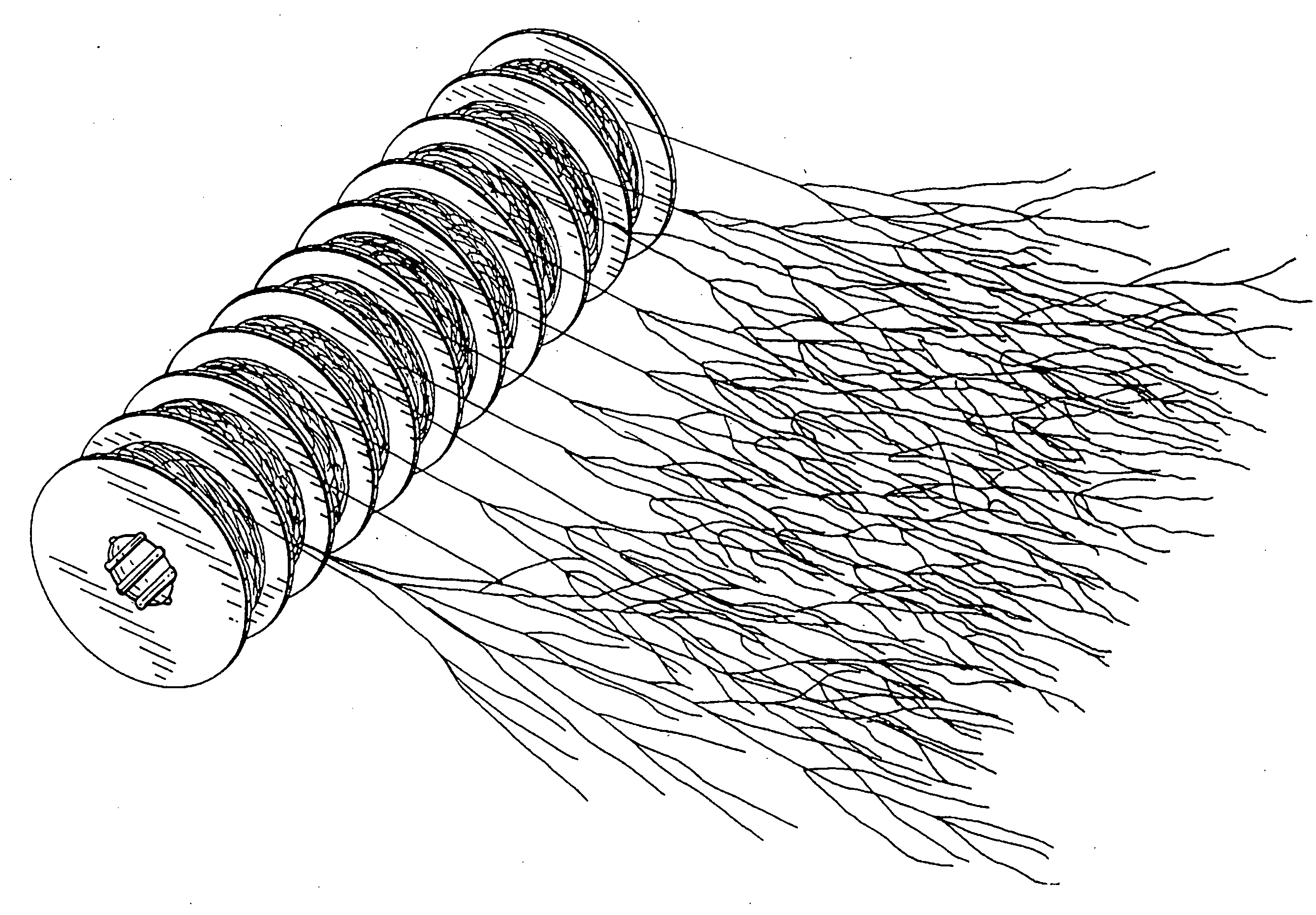
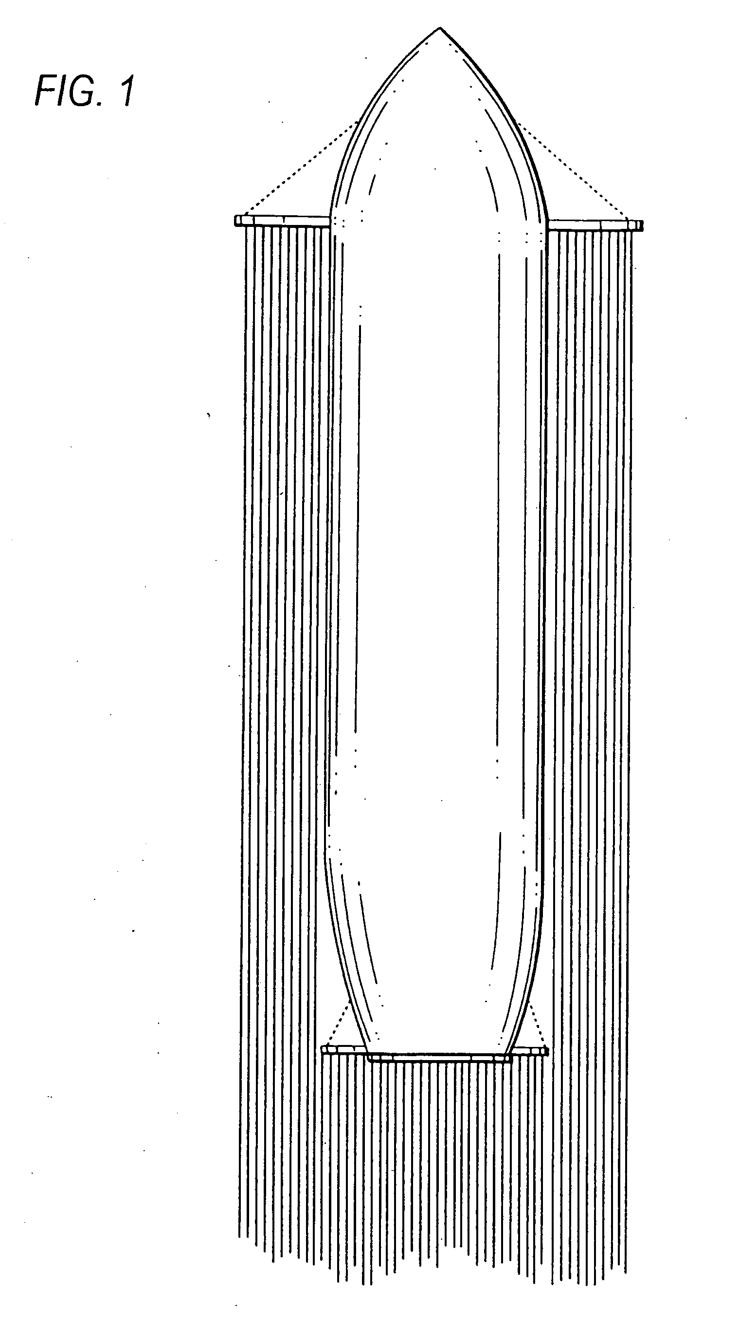
[0026]Referring now to the drawings, (FIG. 1) indicates the coverage pattern of the subsurface towed array / entanglement system and positioning of the main storage and outrigger banks relative to the protected vessel. The main storage bank spans the complete width of the vessel's transom. Adjacent to the main transom bank are two stern quarter outriggers (port and starboard sides). These stern mounted outriggers are designed to deploy extensions of the main transom towed array / entanglement system to the full width of the protected vessel's parallel body and the length of the quarter outriggers is proportional to the difference between the length of the main transom bank and the overall beam of the vessel being protected. The towed stern array / entanglement lines extends aft of the vessel not less than 3000 feet. The forward shoulder outriggers deploy side towed arrays / entanglement lines of not less than 20 feet in width / span, off the port and starboard sides. These side towed arrays / e...


PUM


Abstract

A sub-surface watercraft immobilizing system and method which may be deployed from any vessel to provide primary passive defense against one or more attacking watercraft(s), fitted with marine engine(s). The system is designed to provide practical all round coverage and consists of a sub-surface towed array/entanglement system of wires and/or spectra/nylon lines weighted for neutral buoyancy, deployed from removable/replaceable cartridges that may be disposable or refurbished. The towed array/entanglement system uses outriggers, weighted submersible rollers and spreaders. A system of secondary and possibly tertiary tentacles is deployed from the primary lines just below the water surface to foul and immobilize propellers and engine cooling water intakes. This is a non-lethal system designed to render one or more detected, or undetected, attacking watercraft inoperative or ineffective.

Description

[0001]U.S. patent application Ser. No. 0070 / 017,432, filed Jan. 25, 2007, entitled “Watercraft Arresting System” and associated U.S. Provisional Application No. 60 / 656,979, filed Feb. 28, 2005, entitled “Boat Trap Air Delivery System”.FIELD OF INVENTION[0002]This subject invention relates to systems and methods for immobilizing one or more attacking watercraft including, but not limited by means of a passive towed sub-surface entanglement system, by means of which the attacking watercraft(s) maneuverability is restricted or rendered immobile by entanglement of it's propeller(s) or water intake(s).BACKGROUND OF INVENTION[0003]Maritime piracy (including potential acts of terrorism) against unarmed commercial and non-commercial vessels has become very prevalent in recent years. There were around 160 recorded attacks in 2008, although only a third of this figure resulted in successful attacks. Such attackers have proven that the use of high speed conventionally powered watercraft is hig...

Claims


Application Information

Patent Timeline
IPC IPC(8): B63B17/00B63B35/00B63B38/00
CPCB63G13/00B63B21/66
Inventor GAYTON, RICHARD J.A.
Owner GAYTON RICHARD J A
Why Eureka
Try Eureka