
Filter cartridge, and device and method for cleaning a filter cartridge

a filter cartridge and filter cartridge technology, applied in the direction of filtration separation, cleaning using liquids, separation processes, etc., can solve the problems of laborious and rather costly, limited existing processes, and difficult removal, cleaning and re-insertion of filter media inside the cartridges,

Inactive Publication Date: 2010-12-02
SCHLUMBERGER TECH CORP
View PDF2 Cites 2 Cited by
  • Summary
  • Abstract
  • Description
  • Claims
  • Application Information

AI Technical Summary

Benefits of technology

[0026]According to a preferred embodiment the used filter cartridge is placed within the cleaning device via the coupling arrangement and liquid such as water is added inside the cleaning device. The filter cartridge is then rotated at a sufficient speed to allow the residues to be removed from the filtering media via a combination of the centrifugal forces and the forces from the water. Preferably, a constant flow of water may be maintained by injecting water inside the cleaning device and removing it (or re-circulating through a water circuit) to carry out and / or facilitate the removal of the dislodged residue.
[0030]rotating the reusable filter cartridge at a sufficiently high speed to substantially remove the residues captured inside the filter cartridge through the centrifugal effect caused by the rotation.

Problems solved by technology

Existing processes are generally limited in that they are labor intensive and rather costly.
Also, typically the removal, cleaning and re-insertion of the filtering media inside the cartridges is a rather difficult and labor intensive process.
For instance, one problem experienced in the field is that the filtering media often needs to be carefully compacted to fit within the cartridge a process which is labor intensive and time consuming.

Method used


Image

  • Filter cartridge, and device and method for cleaning a filter cartridge
  • Filter cartridge, and device and method for cleaning a filter cartridge
  • Filter cartridge, and device and method for cleaning a filter cartridge

Examples


Embodiment Construction

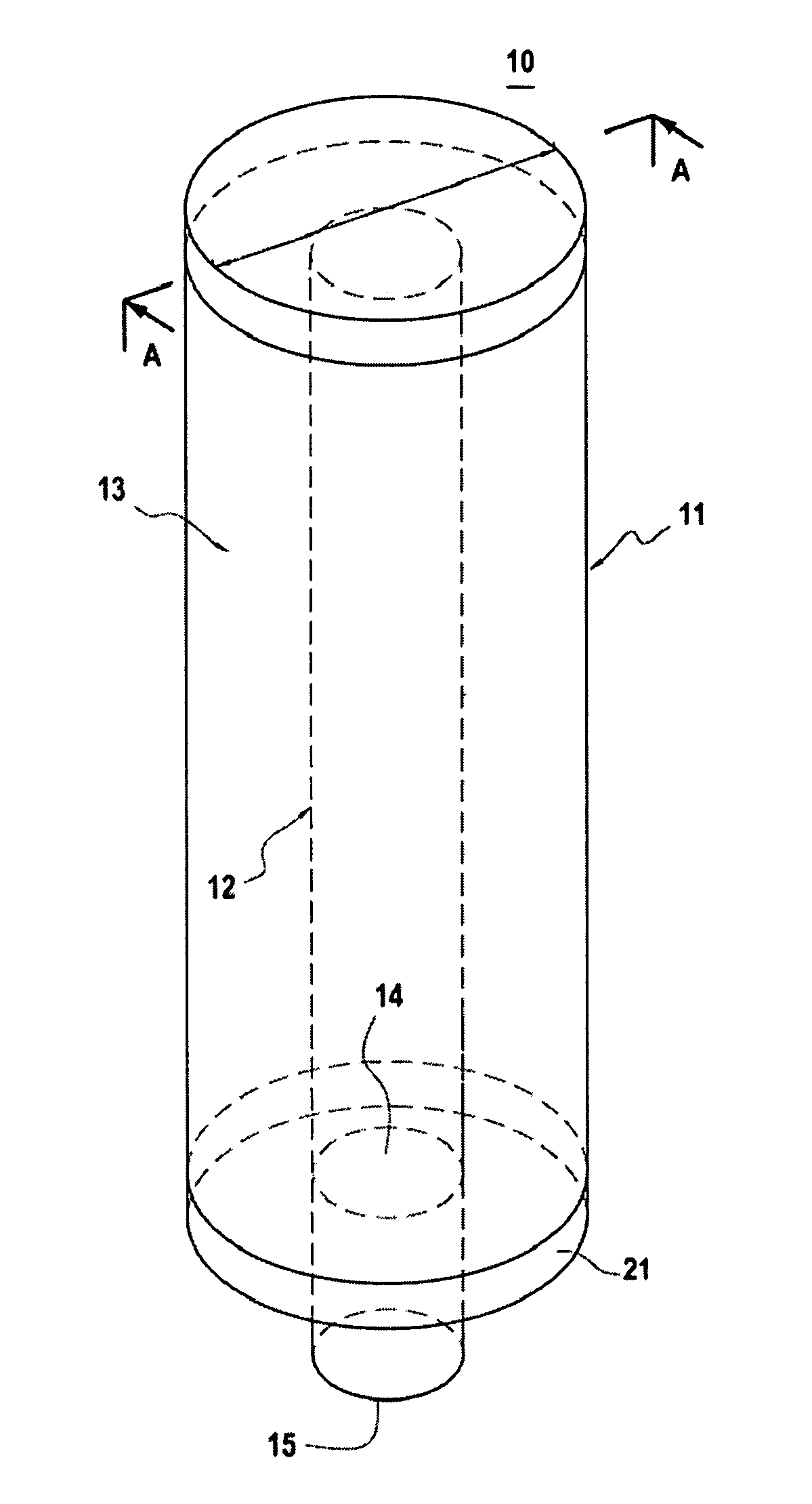
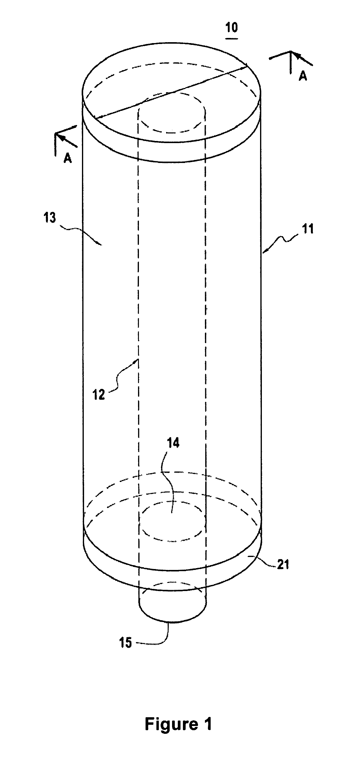
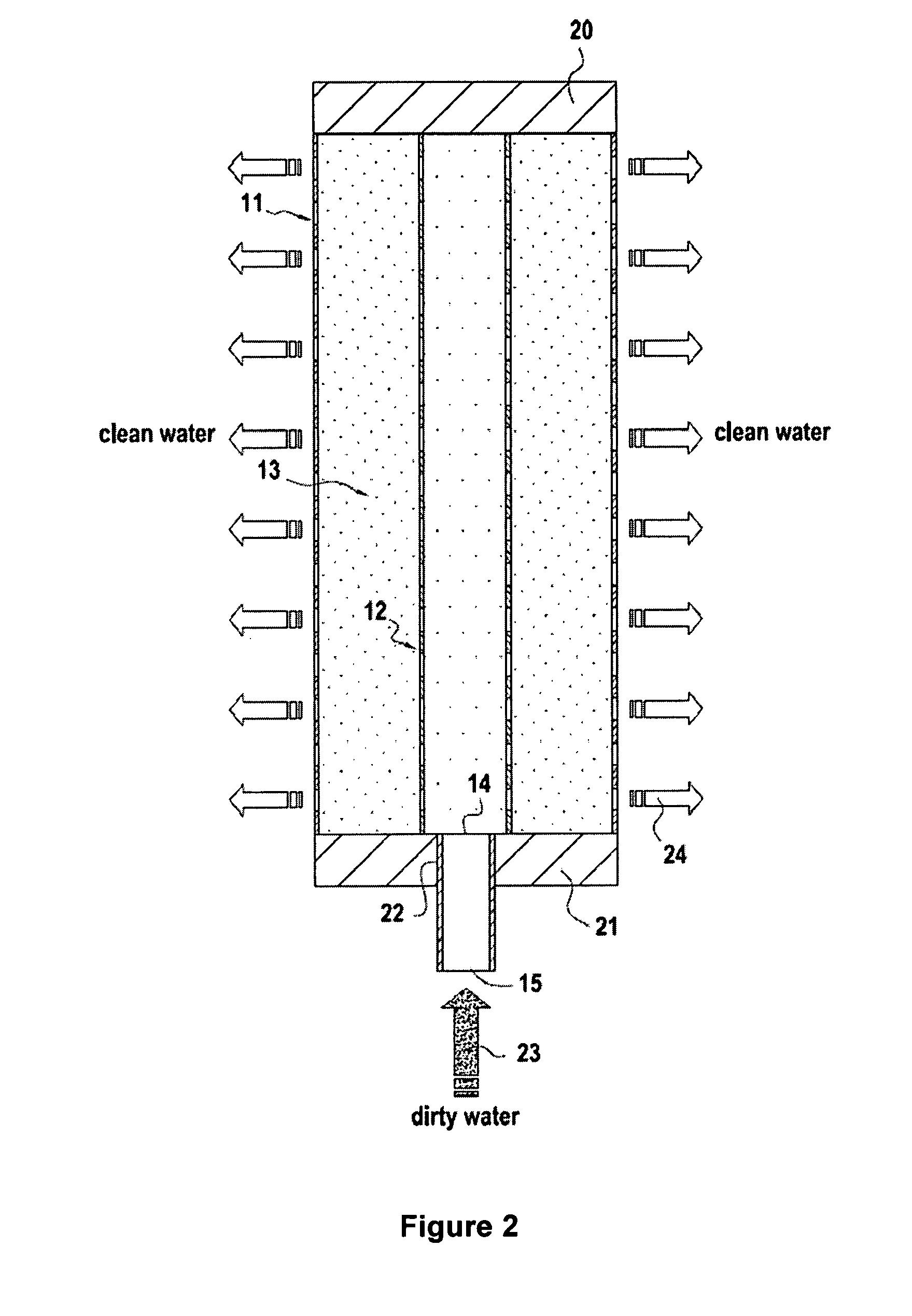
[0037]FIGS. 1 to 3 represent a preferred embodiment of a reusable filter cartridge according to the invention.

[0038]According to FIG. 1, a reusable filter cartridge 10 is shown having a symmetrical structure and comprising an outer pipe 11, having perforations (not shown in FIG. 1) and an inner pipe 12 (shown in dotted lines), having perforations (also not shown in FIG. 1). Inner pipe 12 has a smaller diameter than that of the outer pipe 11. Inner pipe 12 is positioned inside outer pipe 11, thereby defining an annulus space between inner pipe 12 and outer pipe 11. A filtering media 13 is located in this annulus space. The cartridge 10 further comprises first and second lids (not shown in FIG. 1), each lid being secured at opposite ends of the cartridge, one of the lids having a central opening therein which is connected to an opening 14 of the inner pipe 12, for the water to flow out of or into the inner pipe 12. The cartridge 10 also comprises an extending sleeve member 15 adapted ...


PUM

PropertyMeasurementUnit
Centrifugal forceaaaaaaaaaa
Diameteraaaaaaaaaa
Speedaaaaaaaaaa

Abstract

A reusable filter cartridge having a symmetrical structure, the reusable filter cartridge comprising a tubular outer pipe having perforations arranged therein. A tubular inner pipe having perforations is arranged therein, and has a smaller diameter than the diameter of the outer pipe such that an annulus is formed between the outer and inner pipes. A filtering media is disposed in the annulus between the outer and inner pipes. A first and second lid is provided, each being secured at opposite ends of the outer and inner pipes; one of the lids having a central opening therein for water to flow out of or into the inner pipe. The reusable filter cartridge further comprises a coupling arrangement for coupling the filter cartridge with a rotating element of a cleaning device so that the filter media can be cleaned by rotation of the filter cartridge around its axis inside the cleaning device. The invention further includes a cleaning device for cleaning a reusable filter cartridge and a method for cleaning a used filter cartridge.

Description

CROSS-REFERENCE TO RELATED APPLICATIONS[0001]The present application is based on and claims priority to U.S. Provisional Application No. 60 / 989,854, filed 23 Nov. 2007; and International Patent Application No. PCT / EP2008 / 009906, filed 21 Nov. 2008. The entire contents of each are herein incorporated by reference.FIELD OF THE INVENTION[0002]The invention relates to a reusable filter cartridge, and to a cleaning device and a method for cleaning the filter material used in the cartridge without removing the filter material from the cartridge. In particular, the invention relates to a reusable radial flow water filter cartridge which may be used in light water treatment units for treating used water from oil and gas wells.BACKGROUND OF THE INVENTION[0003]In oil drilling processes, water is injected in a well for a variety of reasons which are well known to persons skilled in this art. For instance water may be injected into a reservoir to increase pressure and thereby stimulate producti...

Claims


Application Information

Patent Timeline
IPC IPC(8): B01D41/04B01D35/30
CPCB01D29/13B01D2201/0407B01D41/04
Inventor CORAILLER, CHRISTOPHEPIERRE, LE FOLL
Owner SCHLUMBERGER TECH CORP
Learn More