Molding stamper and method for fabricating same

a molding stamper and stamping technology, which is applied in the direction of manufacturing tools, photomechanical equipment, instruments, etc., can solve the problems of increasing the surface roughness and affecting the production efficiency of the molding stamper

Inactive Publication Date: 2010-12-02
HON HAI PRECISION IND CO LTD
View PDF7 Cites 3 Cited by
  • Summary
  • Abstract
  • Description
  • Claims
  • Application Information

AI Technical Summary

Benefits of technology

[0005]However, this method for fabricating the molding stamper includes many steps, and thus the production efficiency of the molding stamper is rather low. In addition, portions of the seed layer may not be completely stripped off from the electroformed body. When this happens, a surface roughness of the molding stamper is increased. This in turn means that the defect rate of final products made using the molding stamper may be unduly high.

Problems solved by technology

However, this method for fabricating the molding stamper includes many steps, and thus the production efficiency of the molding stamper is rather low.
In addition, portions of the seed layer may not be completely stripped off from the electroformed body.
When this happens, a surface roughness of the molding stamper is increased.
This in turn means that the defect rate of final products made using the molding stamper may be unduly high.

Method used


Image

  • Molding stamper and method for fabricating same
  • Molding stamper and method for fabricating same
  • Molding stamper and method for fabricating same

Examples


Embodiment Construction

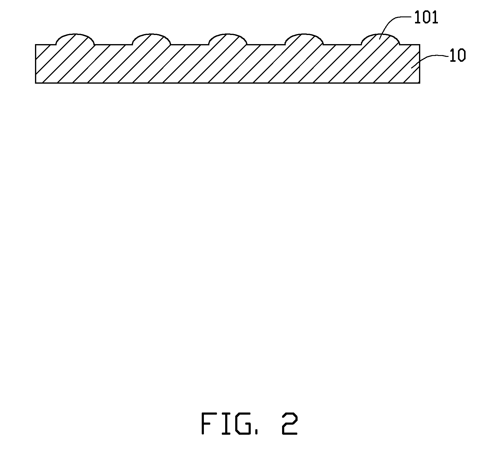
[0010]Embodiments will now be described in detail below with reference to the drawings. In this description, unless the context indicates otherwise, it is assumed that a “microstructure” is a structure which has at least one of three dimensions thereof in the range from about 0.1 micrometers to about 999 micrometers. Similarly, unless the context indicates otherwise, a “microlens” is assumed to have a similar meaning.

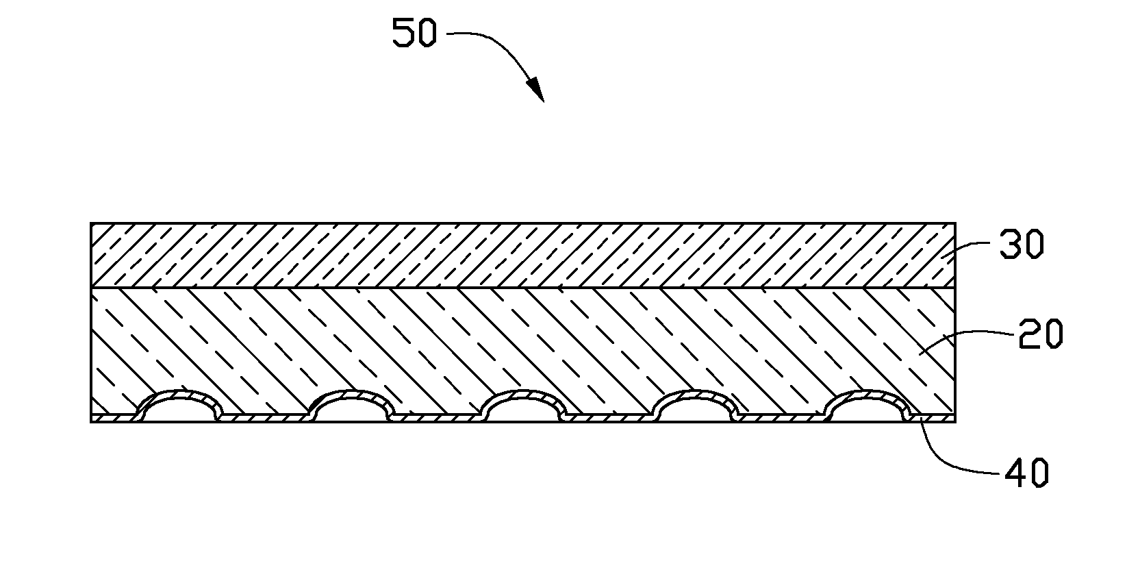
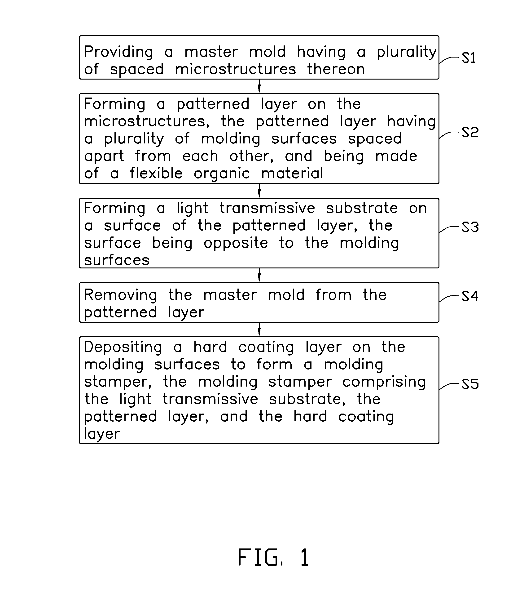
[0011]Referring to FIG. 1, a method for fabricating a molding stamper 50 (see FIG. 6), in accordance with an exemplary embodiment, includes the following steps: step S1, providing a master mold having a plurality of spaced microstructures thereon; step S2, forming a patterned layer on the microstructures, the patterned layer having a plurality of molding surfaces spaced apart from each other, and being made of a flexible organic material; step S3, forming a light transmissive substrate on a surface of the patterned layer, the surface being opposite to the molding surfac...


PUM

PropertyMeasurementUnit
pressureaaaaaaaaaa
temperatureaaaaaaaaaa
pressureaaaaaaaaaa

Abstract

An exemplary method for fabricating a molding stamper includes the following steps. Firstly, a master mold having microstructures spaced apart from each other is provided. Secondly, a patterned layer is formed on the microstructures, the patterned layer having molding surfaces apart from each other, and being made of a flexible organic material. Thirdly, the master mold is removed from the patterned layer. Finally, a hard coating layer is deposited on the molding surfaces to form a molding stamper.

Description

BACKGROUND[0001]1. Technical Field[0002]The present disclosure relates to methods for fabricating molding stampers, and particularly, to a method for fabricating a molding stamper having a pattern for shaping a plurality of microlenses, and a molding stamper fabricated by the method.[0003]2. Description of Related Art[0004]A conventional method for making a molding stamper typically includes the following steps: forming a photoresist layer on a substrate; exposing the photoresist layer to light, and developing the photoresist layer using developer; etching the substrate to form a patterned substrate, and removing the photoresist layer; forming a seed layer on the patterned substrate; electroforming a body on the substrate; and separating the electroformed body from the substrate, and stripping the seed layer off the electroformed body to obtain the molding stamper.[0005]However, this method for fabricating the molding stamper includes many steps, and thus the production efficiency o...

Claims


Application Information

Patent Timeline
Patent Type & Authority Applications(United States)
IPC IPC(8): B29C33/42B29C59/02
CPCB29C33/3857B29C33/565B29C43/021B29C45/2632G03F7/0017B29C2043/3634B29D11/00365B29K2021/00B29L2011/0016B29C2043/025
Inventor HUANG, YUNG-LUN
Owner HON HAI PRECISION IND CO LTD
Why Eureka
Try Eureka