Tail-less LED Control Circuit

a technology of led control circuit and tail-less light, which is applied in the direction of lighting apparatus, electroluminescent light sources, light sources, etc., can solve the problems of reducing the effectiveness of pwm dimming signal b and low dimming contrast, and achieves high contrast pwm dimming and afterglow. , the effect of reducing the intensity of led

Active Publication Date: 2010-12-02
RICHTEK TECH
View PDF4 Cites 12 Cited by
  • Summary
  • Abstract
  • Description
  • Claims
  • Application Information

AI Technical Summary

Benefits of technology

[0009]To achieve the objective mentioned above, the present invention provides a tail-less LED control circuit. The tail-less LED control circuit comprises: a power supply stage having an output terminal which provides electrical power to an LED circuit; an output capacitor coupled to the output terminal; an LED driver circuit coupled to the power supply stage for controlling the power supply stage to provide the electrical power to the LED circuit, the LED driver circuit receiving a PWM dimming signal for adjusting brightness of the LED circuit; and a MOSFET switch coupled to the output capacitor in series, the MOSFET switch switching synchronously with the PWM dimming signal to alleviate LED afterglow.
[0010]When the PWM dimming signal turns OFF the LED circuit during its low state period (referred to as “PWM low period”), the present invention also turns OFF the MOSFET switch to isolate the output capacitor, such that the output capacitor Cout is not discharged via the LED circuit; thus, the LEDs are turned OFF sharply (tail-less). In this PWM low period, only the magnetizing current of the inductor will light up the LED for a very short while. As the inductor magnetizing current reaches zero, the LED stays off for the rest of the PWM low period. Therefore, a high contrast PWM dimming can be achieved by the added MOSFET switch. And since the output capacitor Cout is not discharged during the OFF period, the appropriate voltage level is well kept across the output capacitor Cout. Thus, no re-charging process is required and there is no settling time issue in the next cycle.

Problems solved by technology

Thus, the actual brightness of the LED circuit 30 does not exactly follow the duty ratio of the PWM dimming signal 20, resulting in low dimming contrast and reducing the effectiveness of the PWM dimming signal 20.

Method used


Image

  • Tail-less LED Control Circuit
  • Tail-less LED Control Circuit
  • Tail-less LED Control Circuit

Examples


Embodiment Construction

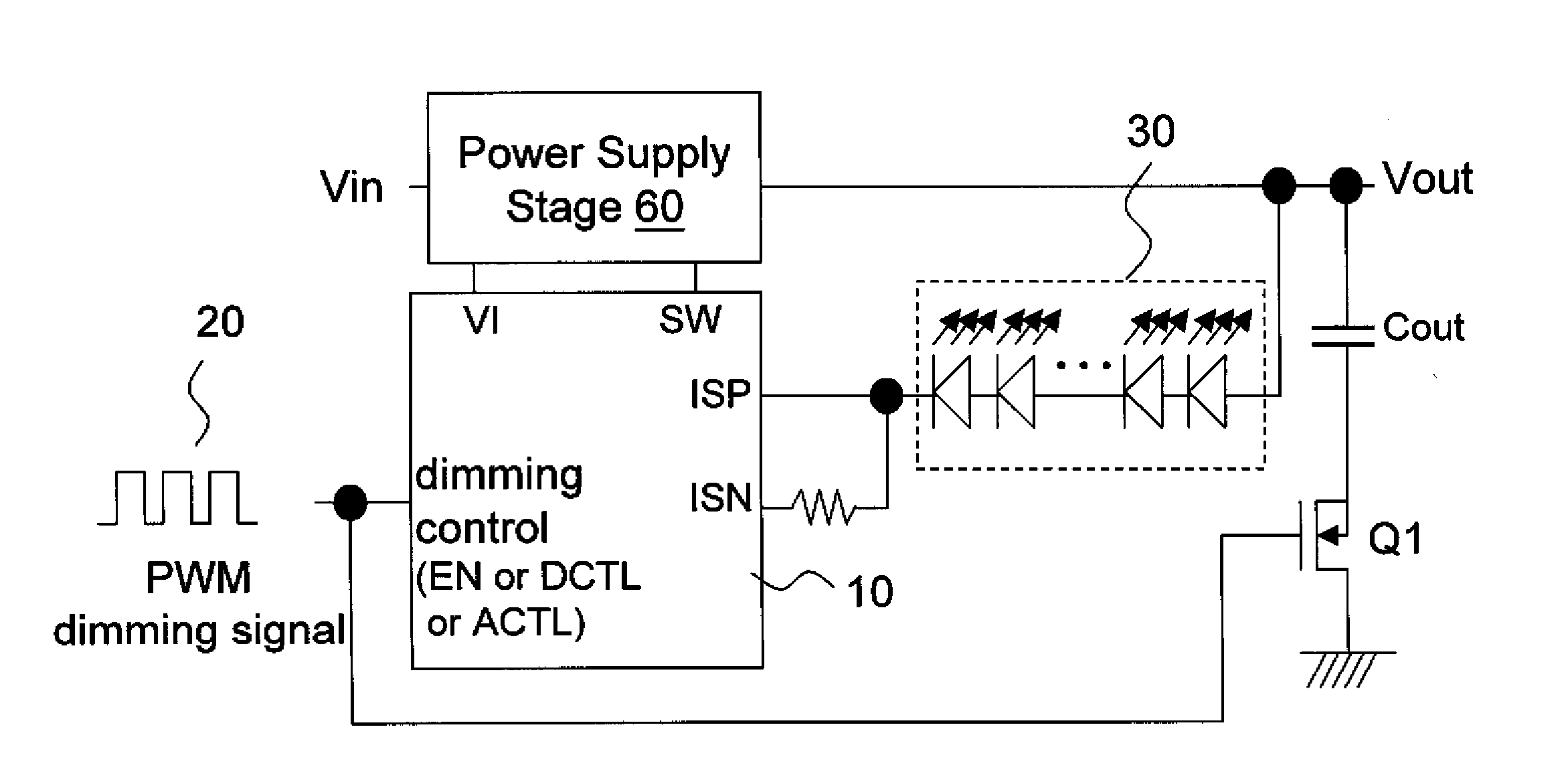
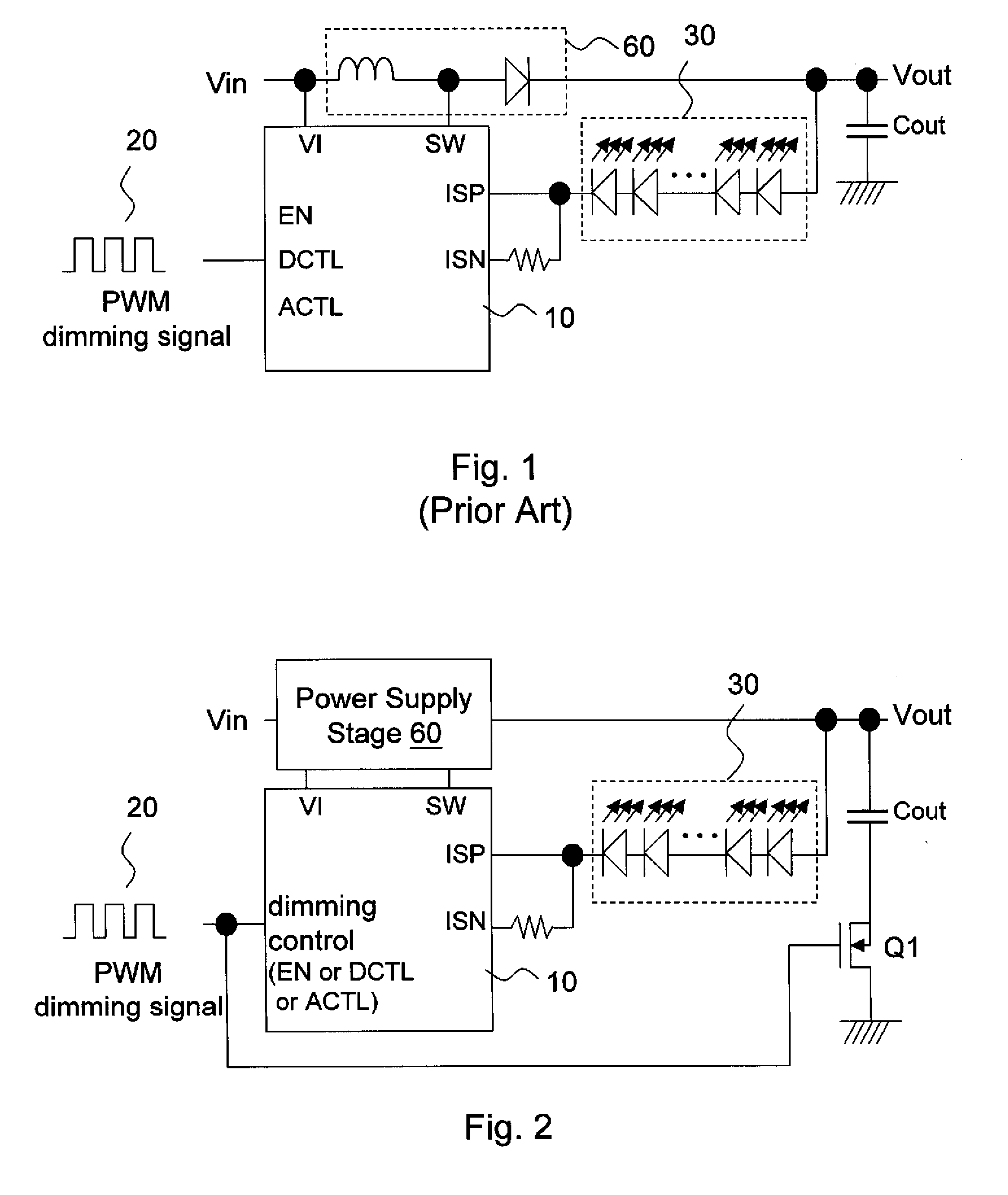
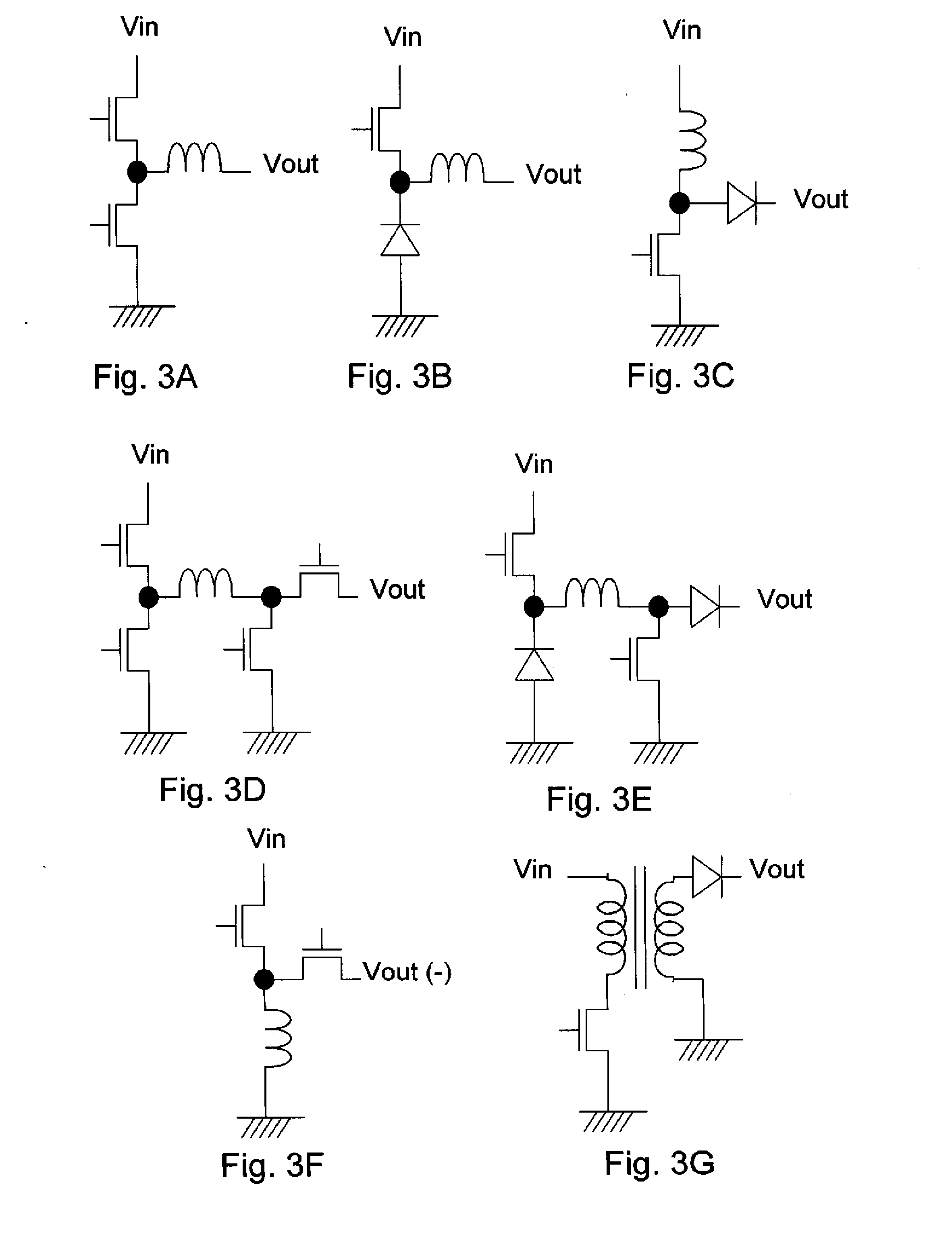
[0021]FIG. 2 shows a first embodiment of the present invention. An LED driver circuit 10 controls a power supply stage circuit 60 to convert an input voltage Vin to an output voltage Vout, which is supplied to an LED circuit 30. The power stage circuit 60 can be (but not limited to) anyone of buck, boost, buck-boost, inverter, and flyback power converters shown in FIGS. 3A-3G. In some cases, the power transistors in FIGS. 3A-3G are integrated into the circuit 10; in other cases, the power transistors are outside of the circuit 10. Referring to FIG. 2, the LED driver circuit 10 receives a PWM dimming signal 20 and turns ON / OFF the LED circuit 30 accordingly to adjust the brightness of the LED circuit 30. The PWM dimming signal 20 may be received via a proper pin provided in the LED driver circuit 10, such as an enable pin EN, a digital control pin DCTL, or an analog control pin ACTL.

[0022]The present invention is characterized by a MOSFET switch connected with the output capacitor Co...


PUM


Abstract

The present invention discloses a tail-less LED control circuit, which includes: a power supply stage having an output terminal which provides electrical power to an LED circuit; an output capacitor coupled to the output terminal; an LED driver circuit coupled to the power supply stage for controlling the power supply stage to provide the electrical power to the LED circuit, the LED driver circuit receiving a PWM dimming signal for adjusting brightness of the LED circuit; and a MOSFET switch coupled to the output capacitor in series, the MOSFET switch switching synchronously with the PWM dimming signal to alleviate LED afterglow, wherein the MOSFET switch includes a body diode having an anode-cathode direction against the discharge direction of the output capacitor.

Description

CROSS REFERENCE[0001]The present invention claims priority to U.S. provisional application No. 61 / 183,380, filed on Jun. 2, 2009.BACKGROUND OF THE INVENTION[0002]1. Field of Invention[0003]The present invention relates to a tail-less light emitting diode (LED) control circuit; particularly, it relates to a tail-less LED control circuit which connects and disconnects an output capacitor in synchronization with a pulse width modulation (PWM) dimming signal, to alleviate LED afterglow (tail).[0004]2. Description of Related Art[0005]FIG. 1 shows a schematic circuit diagram of a conventional LED control circuit. As shown in FIG. 1, an LED driver circuit 10 controls the inductor current in a power supply stage 60 via a switching signal pin SW, such that the power supply stage 60 provides electrical power to an LED circuit 30. The LED driver circuit 10 receives a PWM dimming signal 20; depending on different designs, such PWM dimming signal 20 may be received via an enable pin EN, a digita...

Claims


Application Information

Patent Timeline
Patent Type & Authority Applications(United States)
IPC IPC(8): H05B37/02
CPCY02B20/346H05B33/0818H05B45/3725H05B45/375H05B45/38H05B45/385Y02B20/30
Inventor LIAO, CHIAWEILIU, JING-MENGHSIU, LENG-NIEN
Owner RICHTEK TECH
Why Eureka
Try Eureka