Display driving device and display driving system

a technology of display driving and driving device, which is applied in the direction of electric digital data processing, instruments, computing, etc., can solve the problems of difficult to largely enhance the response speed and the response speed is not improved so much, and achieves enhanced moving image characteristics, high speed, and high speed

Inactive Publication Date: 2010-12-02
RENESAS ELECTRONICS CORP
View PDF0 Cites 30 Cited by
  • Summary
  • Abstract
  • Description
  • Claims
  • Application Information

AI Technical Summary

Benefits of technology

[0021]According to one concrete aspect of the invention, the following is implemented when OD is performed over multiple frames: using a look-up table, a driving gray-scale value is determined from the gray-scale value of an image before display image change and the gray-scale value of the present display image; and this driving gray-scale value is converted into gray scale voltage to carry out driving. It is thereby made possible to vary the gray scale voltage for performing OD according to the number of frames since a change of display images by changing look-up tables according to the number of frames since the change of display images. Luminance response is thereby converged at high speed to enhance moving image characteristics.
[0022]According to another concrete aspect of the invention, the following is implemented when OD is performed over multiple frames: using a look-up table, a first driving gray-scale value is determined from the gray-scale value of an image before display image change and the gray-scale value of the present display image; a second driving gray-scale value is obtained by multiplying the first driving gray-scale value by the value of a monotone decreasing function with the number of frames since the change of display images taken as a variable; and the second driving gray-scale value is converted into gray scale voltage to carry out driving. It is thereby made possible to vary gray scale voltage for performing OD according to the number of frames since a change of display images. Luminance response is thereby converged at high speed to enhance moving image characteristics.
[0023]According to further another concrete aspect of the invention, the following are provided: a display pattern setting register for setting a number of periods during which an identical display image continues; an image change detection circuit for detecting that the display gray-scale value one period before and the present display gray-scale value are different from each other; and a counter that operates according to the display pattern setting register and the detection timing of the image change detection circuit. A display gray-scale value is stored in a storage circuit in a drive circuit according to the value of the counter and further the look-up tables are changed according to the counter value. It is thereby made possible to reliably perform overdrive for multiple frames and vary gray scale voltage for performing OD according to the number of frames since a change of images. Luminance response is thereby converged at high speed to enhance moving image characteristics.
[0024]According to further another concrete aspect of the invention, the following are provided: a display pattern setting register for setting a number of periods during which an identical display image continues; an image change detection circuit for detecting that the display gray-scale value one period before and the present display gray-scale value are different from each other; and a counter that operates according to the display pattern setting register and the detection timing of the image change detection circuit. A display gray-scal

Problems solved by technology

When they get out of sync, OD driving is performed only during one-frame period and as a result, response speed is not improved so much.
When the content of one-segment broadcasting or the like is displayed with the above conventional technology, a problem arises even when change of display data in the one-segment

Method used


Image

  • Display driving device and display driving system
  • Display driving device and display driving system
  • Display driving device and display driving system

Examples


first embodiment

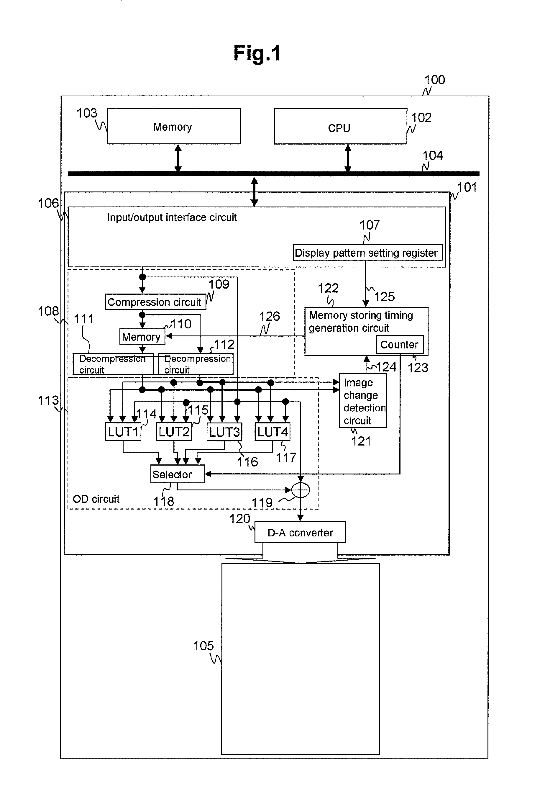
[0068]FIG. 1 illustrates an example of the block configuration of a display driving device in a first embodiment of the invention. Reference numeral 100 denotes a display driving system applied to a cellular phone or the like; 101 denotes a display driving device such as a liquid crystal driver; 102 denotes a central processing unit (CPU) that comprehensively controls the display driving system 100; 103 denotes a memory such as RAM for storing display data and the like; 104 denotes an internal bus; and 105 denotes a display panel that is driven by the display driving device 101 and makes display. In the description of this embodiment, attention is paid to display gray-scale value as display data. Even though not explicitly stated, display data refers to display gray-scale value.

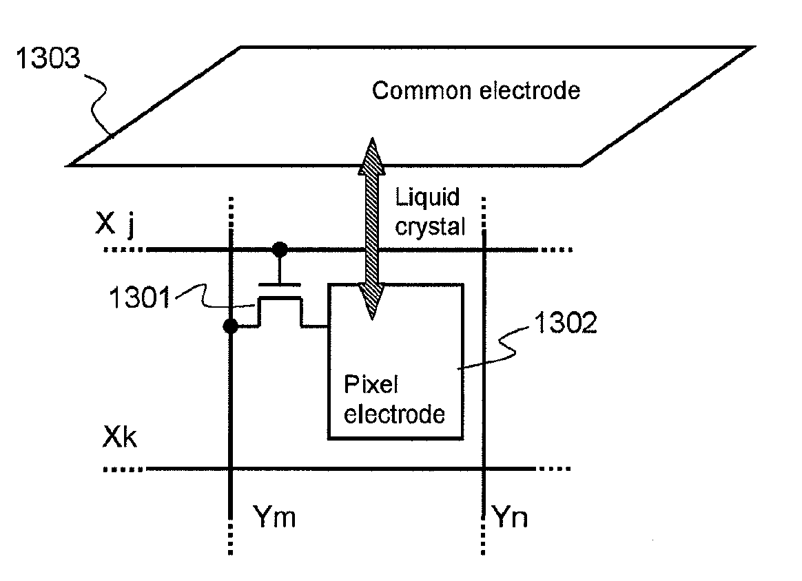
[0069]The display panel 105 may be liquid crystal panel, organic EL panel, PDP, FED, electronic paper, or the like as long as it is a display panel. FIG. 13 schematically illustrates the configuration of a di...

second embodiment

[0081]Description will be given to a second embodiment with reference to FIG. 5, FIG. 6, FIG. 7, and FIG. 8. In general, small liquid crystal panels of cellular phones and the like are slower in response than liquid crystal panels for televisions because of structure, cost, and the like. Cellular phones and in-vehicle liquid crystal panels are used in a severe use environment and they must accommodate to a wide temperature range from high temperature to low temperature. It is commonly known that liquid crystal panels become slow in response in low temperature. If a high-speed moving image is displayed in a liquid crystal panel very slow in response, a problem arises. The brightness is averaged and the display image is evenly turned gray or the like and becomes invisible. As an example, it will be assumed that the image of gray vertical lines illustrated in FIG. 7 is horizontally scrolled with the same magnitude as the width of each vertical line. It will be assumed that the brightne...

third embodiment

[0084]Description will be given to a third embodiment with reference to FIG. 9 and FIG. 10. The third embodiment performs the same operation as the first embodiment and the second embodiment; however, it is different from the first embodiment and the second embodiment in the configuration of the overdrive circuit 113. The overdrive circuit 113 in the third embodiment can be substituted for the overdrive circuits in the first embodiment and the second embodiment. FIG. 9 illustrates an example of the block configuration of the overdrive circuit 113 in the third embodiment and a peripheral circuit thereof. The third embodiment is provided with only one look-up table (LUT). In the third embodiment, the output value of the look-up table 114 is multiplied by the value of a monotone decreasing function with the count value of the memory storing timing counter 123 taken as a variable at a monotone decreasing function multiplication circuit 901.

[0085]FIG. 10 is a drawing explaining the opera...


PUM


Abstract

Overdrive over multiple frames is made more efficient in a display device drive circuit that drives a display device so slow in response that target brightness is not reached even after overdrive is performed for one frame. When a display gray scale is changed from a first gray scale to a second gray scale, a display driving device varies overdrive driving voltage according to the number of frames since the point of time of the change. This makes it possible to obtain high-speed luminance response. When the number of frames for which an identical image is continuously displayed is known beforehand, the number of frames is set in a display pattern setting register and a function of detecting timing of a change of images is provided. This enables efficient overdrive. At low temperature, further, a display image is updated once for several frames according to temperature information. This enhances the visibility of the image.

Description

CLAIM OF PRIORITY[0001]The Present application claims priority from Japanese patent application JP 2009-126182 filed on May 26, 2009, the content of which is hereby incorporated by reference into this application.FIELD OF THE INVENTION[0002]The present invention relates to display driving devices that drive a display panel and further display driving systems and in particular to a technology effectively applicable to, for example, the improvement of the moving image characteristics of a device low in response.BACKGROUND OF THE INVENTION[0003]In recent years, television pictures such as one-segment images have been increasingly commonly displayed in mobile devices such as cellular phones and car navigation devices as an in-vehicle display device. With respect to in-car use, liquid crystal display panels have come to be used also in instrument panels and the like because of design or the like.[0004]It is known that liquid crystal display devices are generally become slower in luminanc...

Claims


Application Information

Patent Timeline
IPC IPC(8): G09G5/10G09G5/00
CPCG09G3/3648G09G2310/027G09G2320/0252G09G2320/0261G09G2320/041G09G2340/16
Inventor KATAYAMA, YUKARIAKAI, AKIHITOKUROKAWA, YOSHIKIUCHIDA, YUSUKE
Owner RENESAS ELECTRONICS CORP
Why Eureka
Try Eureka