Inkjet printer

Inactive Publication Date: 2010-12-02
MIMAKI ENG
View PDF2 Cites 4 Cited by
  • Summary
  • Abstract
  • Description
  • Claims
  • Application Information

AI Technical Summary

Problems solved by technology

Though the inkjet printer disclosed in JP-A-2003-022890 can rapidly dry the ink, the inkjet printer has a disadvantage that it is necessary to make the power of the microwaves supplied to the wave guide strong or slow down the feeding speed of the medium moving through the wave guide so as to lengthen the time of irradiating the medium with microwaves because the power of the microwaves to be absorbed in the ink is not so strong.

Method used


Image

  • Inkjet printer
  • Inkjet printer
  • Inkjet printer

Examples


first embodiment

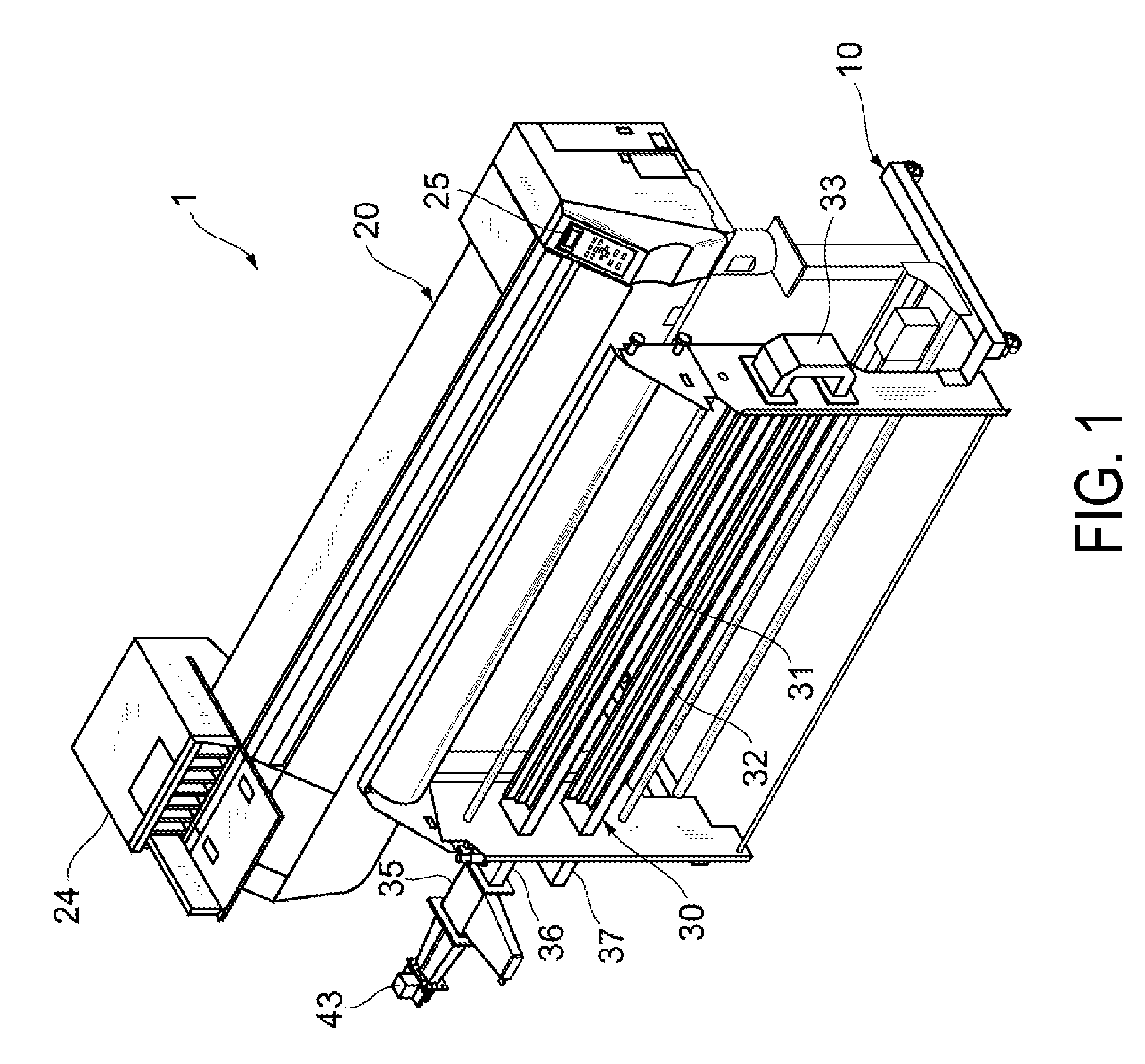
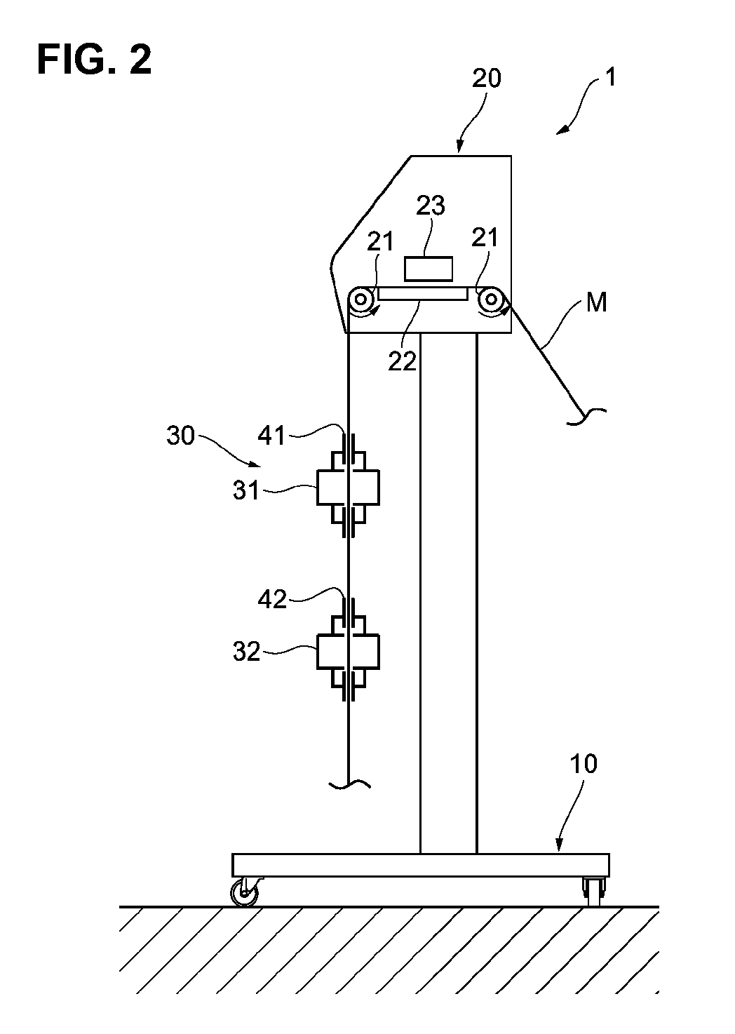
[0030]FIG. 1 is a perspective view showing an inkjet printer according to a first embodiment and FIG. 2 is a sectional view of the inkjet printer shown in FIG. 1.

[0031]As shown in FIG. 1 and FIG. 2, the inkjet printer 1 according to the first embodiment includes a printer unit 20 which is mounted on a base 10 to eject ink onto a medium M, and a wave guide 30 for drying the ink deposited on the medium M by the printer unit 20. The medium M is a sheet-like medium made of paper, silk, cotton, vinyl chloride or the like. The ink may be dye-type ink such as acid dye, reactive dye, and substantive dye or organic solvent-type ink such as solvent ink.

[0032]The printer unit 20 includes feeding rollers 21 for feeding the medium M, an inkjet head 23 for ejecting ink onto the medium M on the platen 22, a toner section 24 in which ink to be ejected from the inkjet head 23 is stored, and an operation section 25 for allowing the manipulated input of a user.

[0033]FIG. 3 is a perspective view of a w...

second embodiment

[0064]Hereinafter, the second embodiment will be described in detail. FIG. 7 is a perspective view of an inkjet printer according to this embodiment.

[0065]As shown in FIG. 7, the inkjet printer la according to the second embodiment includes a printer section 20 which is mounted on a base 10 to eject ink onto a medium M and a wave guide 30a for drying the ink deposited on the medium M by the printer section 20.

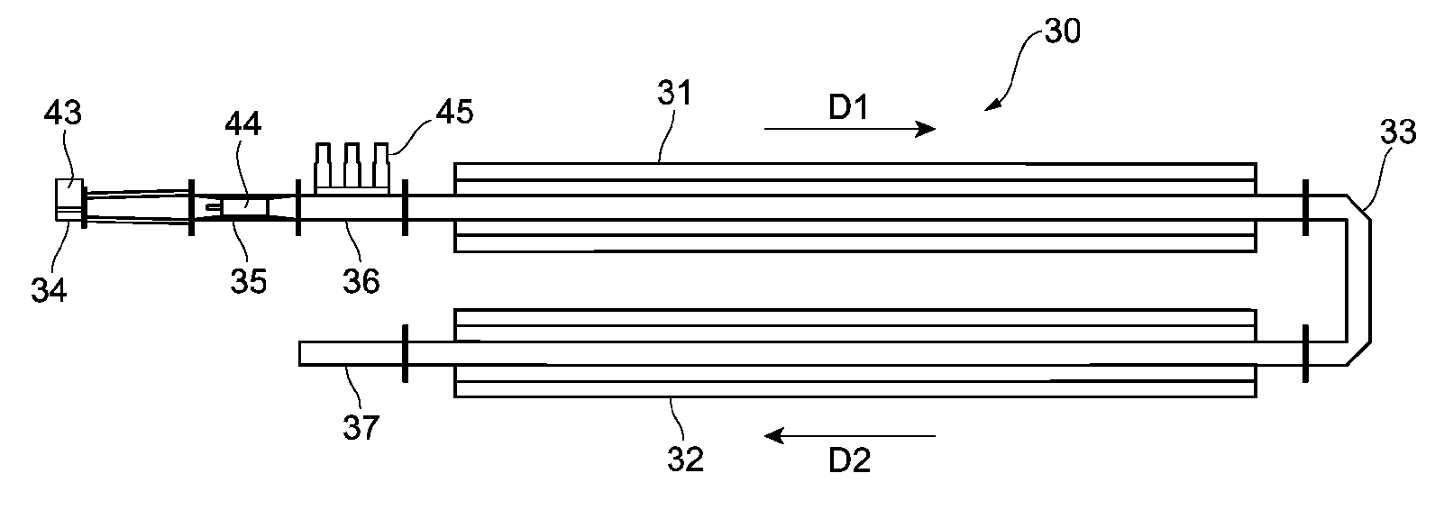
[0066]FIG. 8 is a perspective view of the wave guide and FIG. 9 is a plan view of the wave guide. As shown in FIG. 8 and FIG. 9, the wave guide 30a is a long wave guide of which section is rectangular and which is bent at its middle portion into a U-like shape so as to have a two-stage structure. The wave guide 30a includes wave guide main bodies 31, 32, a curve section 33, an electromagnetic wave supplying section 34, a propagation preventing section 35, a matching section 36, a termination section 37, and a rotary reflection section 38. That is, the wave guide 30a is formed b...


PUM


Abstract

An inkjet printer includes an ejector, a wave guide, an electromagnetic wave supplier, and a reflector. The ejector is configured to eject ink toward a medium. Through the wave guide, the medium with the ink ejected by the ejector is inserted. The electromagnetic wave supplier is disposed at a start end of the wave guide to supply electromagnetic waves to the wave guide. The reflector is disposed at a terminal end of the wave guide to reflect the electromagnetic waves supplied by the electromagnetic wave supplier.

Description

CROSS-REFERENCE TO RELATED APPLICATIONS[0001]The present application is a continuation application of International Application No. PCT / JP2009 / 067351, filed Oct. 5, 2009, which claims priority to Japanese Patent Application No. 2008-260723, filed Oct. 7, 2008, and Japanese Patent Application No. 2008-260808, filed Oct. 7, 2008. The contents of these applications are incorporated herein by reference in their entirety.BACKGROUND OF THE INVENTION[0002]1. Technical Field[0003]The present invention relates to an inkjet printer.[0004]2. Background Art[0005]In an inkjet printer, printing is conducted by ejecting dye-type ink such as acid dye, reactive dye, and substantive dye or pigment-type ink containing organic solvent such as solvent ink, onto a surface or both front and back surfaces of a sheet-like medium (recording medium) made of paper, silk, cotton, vinyl chloride, or the like. Especially in the industrial field, in such an inkjet printer, it is important to effectively dry a medi...

Claims


Application Information

Patent Timeline
Patent Type & Authority Applications(United States)
IPC IPC(8): B41J2/14
CPCB41J11/002H05B6/802H05B2206/046B41J11/00216B41J2/01
Inventor ONOZAWA, YOSHIKIYAMADA, RYUJIMINEMURA, AKIRATAKANO, TERUHISA
Owner MIMAKI ENG
Why Eureka
Try Eureka