Image processing apparatus, image processing method, and storage medium

a technology of image processing and image processing method, applied in the field of image display technique, can solve the problems of large amount of calculation, difficult to observe flicker, and image lag (tail-blurring) in an area, and achieve the effect of reducing image lag in an area

Inactive Publication Date: 2010-12-02
CANON KK
View PDF2 Cites 15 Cited by
  • Summary
  • Abstract
  • Description
  • Claims
  • Application Information

AI Technical Summary

Benefits of technology

[0013]According to the present invention, it is possible to reduce an image lag in an area with motion which is caused when an image is displayed at a double speed by usin...

Problems solved by technology

This can therefore make it difficult to observe flicker.
The first method “frame (field) interpolation based on motion compensation” has the problem that since it requires the processing of generating an intermediate image by using the image data of adjacent frames, a large amou...

Method used


Image

  • Image processing apparatus, image processing method, and storage medium
  • Image processing apparatus, image processing method, and storage medium
  • Image processing apparatus, image processing method, and storage medium

Examples


first embodiment

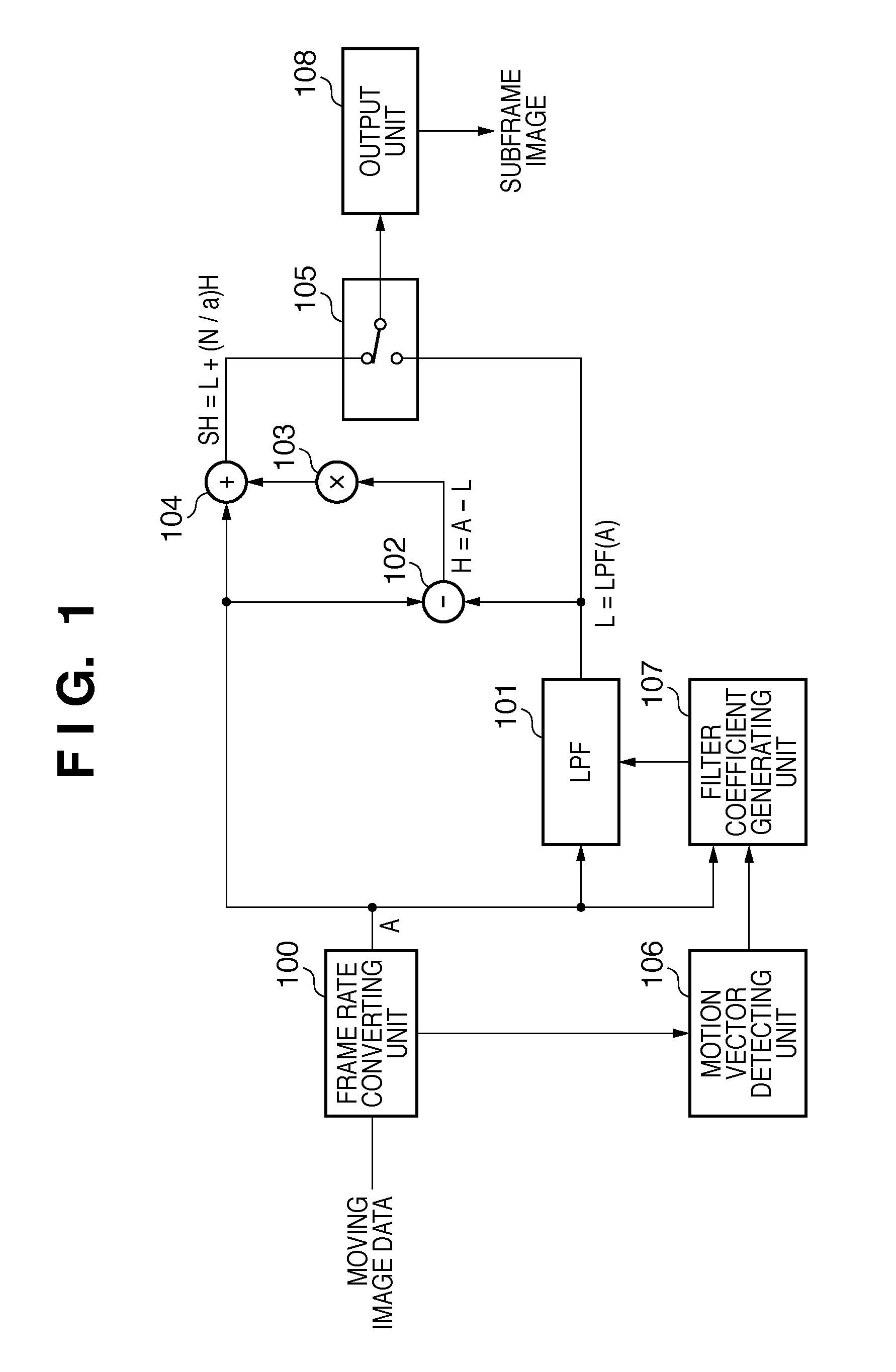
[0033]FIG. 1 is a block diagram showing the arrangement of an image display apparatus according to the first embodiment. Referring to FIG. 1, reference numeral 100 denotes a frame rate converting unit; 101, a low-pass filter (to be referred to as an LPF hereafter); 102, a subtracter; 103, a multiplier; 104, an adder; 105, a switch; 106, a motion vector detecting unit; 107, a filter coefficient generating unit; and 108, an output unit.

[0034]The frame rate converting unit 100 acquires moving image data in one frame unit, and generates N subframe images from one frame image. More specifically, the frame rate converting unit 100 includes a frame memory (not shown), and stores input moving image data as an input image in the frame memory on a frame basis. The frame rate converting unit 100 then generates N subframe images as replicated images by reading one frame image of interest (input image) N times at the N times higher frequency than input video data. Assume that in this case, one s...

second embodiment

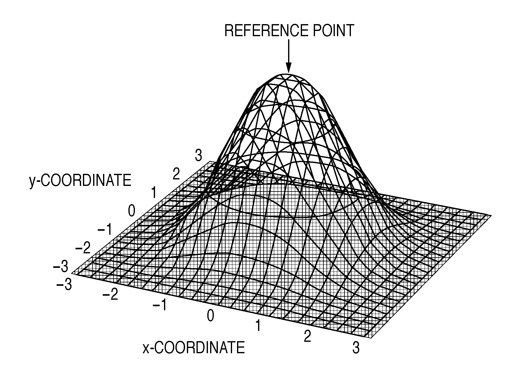
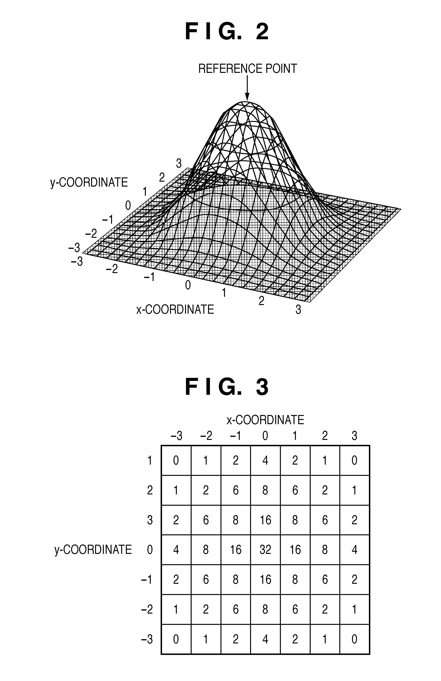
[0087]In the first embodiment, the filter coefficient generating unit 107 calculates the coordinates (X, Y) of a reference point according to equations (4). However, the way of obtaining a reference point is not limited to this method. In some cases, the absolute value of each component of a motion vector V(x, y) greatly exceeds the filter size (kernel size) of the filter function. Assume that the absolute value of each component of a motion vector is very large. In this case, when a reference point moves, the filter shape may become unbalanced because, for example, the maximum size of the filter size (kernel size) is limited on a circuit. That the filter shape becomes unbalanced is that, for example, the filter size becomes asymmetric about the center of the filter function in the x direction. It is possible to use the asymmetric function. However, it is also possible to impose a limitation on the moving amount of a reference point.

[0088]In the second embodiment, a limitation may b...

third embodiment

[0092]In the first and second embodiments, the LPF 101 performs spatial frequency component splitting. In the third embodiment, a high-pass filter (to be referred to as an HPF hereinafter) performs spatial frequency component splitting. An HPF may be, for example, a filter function represented by a Laplacian filter which determines filter coefficients based on a spatial second derivative.

[0093]FIG. 12 is a block diagram showing the arrangement of an image display apparatus according to the third embodiment. The same reference numerals as in FIG. 1 denote the same constituent elements as those in the first embodiment. In the third embodiment, the operations of a frame rate converting unit 100, motion vector detecting unit 106, and output unit 108 are the same as those in the first embodiment.

[0094]Unlike in the first embodiment, a filter coefficient generating unit 107 outputs filter coefficient used by an HPF 1201. The filter coefficient generating unit 107 obtains filter coefficien...


PUM


Abstract

According to one aspect of the invention, an image processing apparatus comprises: a unit configured to obtain an input image and a subsequent image; a unit configured to obtain N replicated images from the input image; a generating unit configured to generate a low-frequency enhanced image; a subtraction unit configured to generate a high-frequency enhanced image; a synthesizing unit configured to generate a high-frequency output image; and an output unit configured to select and output one of the low-frequency enhanced image and the high-frequency output image. The generating unit comprises a unit configured to obtain a motion vector of an object, and a filter unit configured to apply the filter to pixels around a specified pixel position Q in the replicated image, to obtain a pixel value at a pixel position P in the low-frequency enhanced image.

Description

BACKGROUND OF THE INVENTION[0001]1. Field of the Invention[0002]The present invention relates to an image display technique for improving a moving image resolution.[0003]2. Description of the Related Art[0004]Recently, commercially available moving image display apparatus for television and the like include so-called liquid crystal displays, plasma displays, and FED displays as well as CRTs. Thus, there are various moving image display apparatus. Each type of moving image display apparatus is designed to reduce motion blurring and flicker by N-folding the frame frequency (frame rate) of an input image signal (that is, dividing one frame into N subframes) and then displaying the resultant image.[0005]The user of a display apparatus designed to emit light almost all the time in a frame time, for example, a hold-type display apparatus, observes relatively large motion blurring. When the user pursues (follows an area of motion in a moving image with his / her gaze), he / she observes larger...

Claims


Application Information

Patent Timeline
IPC IPC(8): H04N5/91
CPCG06T3/4053G09G3/20G09G2320/0257H04N7/0132G09G2320/106G09G2340/0435G09G2320/0261
Inventor MIZUNO, RYOSUKE
Owner CANON KK
Why Eureka
Try Eureka