

Fixing device and image forming apparatus including fixing device
a technology of fixing device and fixing roller, which is applied in the direction of electrographic process apparatus, instruments, optics, etc., can solve the problems of increasing power consumption, deteriorating heat generation efficiency, and not following the temperature of the fixing roller when a process speed is increased, so as to reduce the warm-up time, prevent deterioration of heat generation efficiency, and stable heat generation
- Summary
- Abstract
- Description
- Claims
- Application Information
AI Technical Summary
Benefits of technology
Problems solved by technology
Method used
Image

Examples
first embodiment
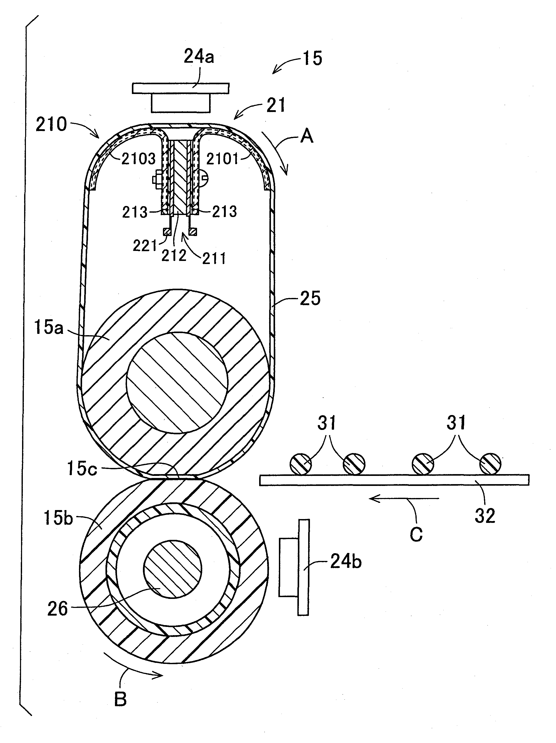
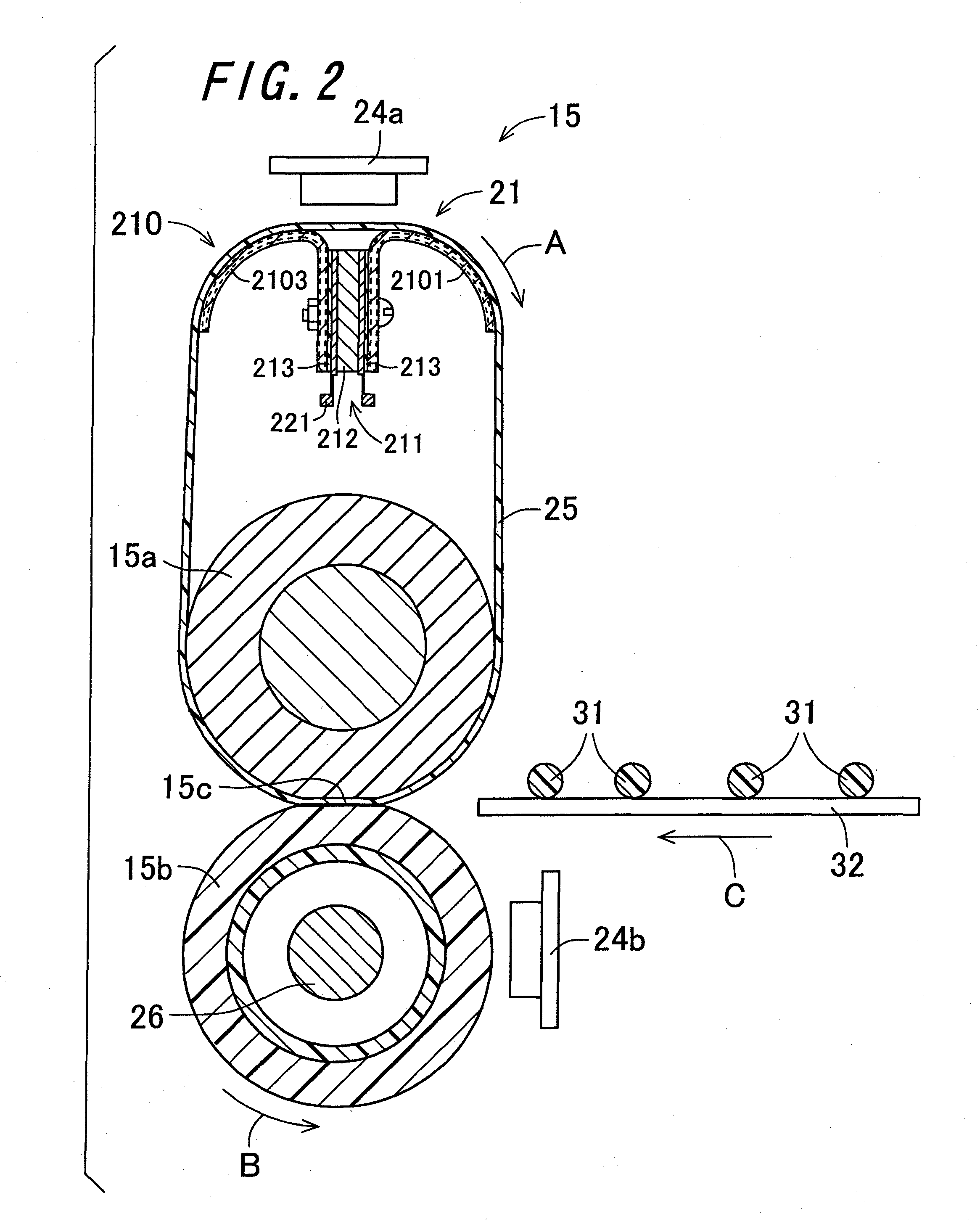
[0114]FIG. 2 is a view showing the structure of the fixing device 15 according to the invention. The fixing device 15 includes a fixing roller 15a serving as a first fixing member, a pressure roller 15b serving as a second fixing member, a fixing belt 25 serving as an endless-shaped belt, and a heating member 21. In the fixing device 15, the fixing belt 25 is supported around the fixing roller 15a and the heating member 21 with tension, and the pressure roller 15b is disposed so as to face the fixing roller 15a, with the fixing belt 25 interposed therebetween. Moreover, the fixing roller 15a and the heating member 21 are arranged substantially in parallel with each other in an axial direction of the fixing roller 15a. With this arrangement, the fixing belt 25 supported around the fixing roller 15a and the heating member 21 with tension can be prevented from running windingly during its sliding movement, wherefore the durability of the fixing belt 25 can be maintained at a high level...
second embodiment
[0215]FIG. 15 is a view showing the configuration of a fixing device 440 according to the invention. The fixing device 440 is a fixing device of two-stage fixing type, and includes a first fixing section 450 that performs primary fixing of the unfixed toner images 31 onto the recording paper sheet 32 under application of heat and pressure, and a second fixing section 460 that is arranged on the downstream side in the conveyance direction of the recording paper sheet 32 from the first fixing section 450 and performs secondary fixing of the toner images 31 after the primary fixing onto the recording paper sheet 32 under application of heat and pressure. The first fixing section 450 and the second fixing section 460 are arranged side by side in the horizontal direction. In the fixing device 440, the first fixing section 450 and the second fixing section 460 are the fixing device 15 of the above-described embodiment that includes the heating member, in which the heat radiating member ha...
third embodiment
[0245]FIG. 16 is a view showing the configuration of a fixing device 470 according to the invention. The fixing device 470 is a fixing device of two-stage fixing type, and includes a first fixing section 480 that performs primary fixing of the unfixed toner images 31 onto the recording paper sheet 32 under application of heat and pressure, and a second fixing section 490 that performs secondary fixing of the toner image 31 after the primary fixing onto the recording paper sheet 32 under application of heat and pressure, the second fixing section being configured by a pair of heating and pressure rollers 491 that are provided with a heating section in an interior thereof, and are in pressure-contact with each other, and being arranged on the downstream side in the conveyance direction of the recording paper sheet 32 with respect to the first fixing section 480. The first fixing section 480 and the second fixing section 490 are arranged side by side in the horizontal direction. In the...
PUM
 Abstract
Description
Claims
Application Information