
Implant fixture remover

a technology for removing fixtures and fixing brackets, which is applied in the field of medical fixture removal devices, can solve the problems of not being able to be inserted or pulled out any more, affecting the safety of patients, so as to prevent side effects of operation, minimize the damage of alveolar bone, and simple and standard operation

Inactive Publication Date: 2010-12-02
HEO YOUNG KU
View PDF15 Cites 17 Cited by
  • Summary
  • Abstract
  • Description
  • Claims
  • Application Information

AI Technical Summary

Benefits of technology

[0010]An advantage of some aspects of the invention is that it provides an implant fixture remover which can apply a strong removing torque of the maximum 1,000 Ncm to a damaged implant fused to a bone so as to rapidly remove a fixture with a simple and standardized treatment while minimizing the removal or damage of a bone around the fixture, thereby guaranteeing the convenience and safety for use.
[0011]Another advantage of some aspects of the invention is that it provides an implant fixture remover which can improve the safety of treatment by safely removing a fixture without cutting out the surrounding alveolar bone and can greatly reduce the time for the treatment, when a fixture connector is damaged due to an excessive torque in the process of planting the fixture and cannot be inserted or pulled out any more.
[0024]According to the above-mentioned implant fixture remover, since useless fixtures damaged, destroyed, or having surrounding bone tissues destroyed can be separated and removed from the alveolar bone while minimizing the damage of the alveolar bone with a simple and standardized operation, it is possible to prevent side effects of the operation due to the increasing site of the alveolar bone to be cut off, thereby enhancing the safety of the operation and greatly reducing the time of the operation.
[0025]It is possible to plant a new implant with the same diameter just after removing the fixture, and to regenerate the destroyed bone tissue in the top of the fixture.
[0026]Although the invention has been applied to the dental field, the invention can be easily applied to plastic surgical and orthopedic fields using a backbone implant or the like.

Problems solved by technology

On the other hand, in the process of planting a fixture, a fixture connector may be damaged due to an excessive torque and thus may not be inserted or pulled out any more.
A fixture inserted into a human bone and successfully fused to the bone may not be retained any more due to the loss of the bone around the implant resulting from an inflammation caused around the implant with the lapse of time.
In the past, since a tool for removing the fixture with such a magnitude of torque was not provided, the bone around the fixture was greatly destroyed and then the fixture was separated and removed.
However, when the bone around the fixture was cut out and the fixture was removed in this way, a fixture could not be re-planted due to the great loss of the bone or another bone transplanting operation had to be performed to reconstruct the destroyed bone.
Accordingly, the operation was made to be greatly complex, thereby causing inconvenience to a patient and elongating the treatment time.

Method used


Image

  • Implant fixture remover
  • Implant fixture remover
  • Implant fixture remover

Examples


Embodiment Construction

[0032]Hereinafter, an implant fixture remover according to an exemplary embodiment of the invention will be described in detail with reference to the accompanying drawings. It should be noted that like elements or components are referenced by like reference numerals in the drawings. The known functions or configurations are not described in the following description so as not to make the gist of the invention vague.

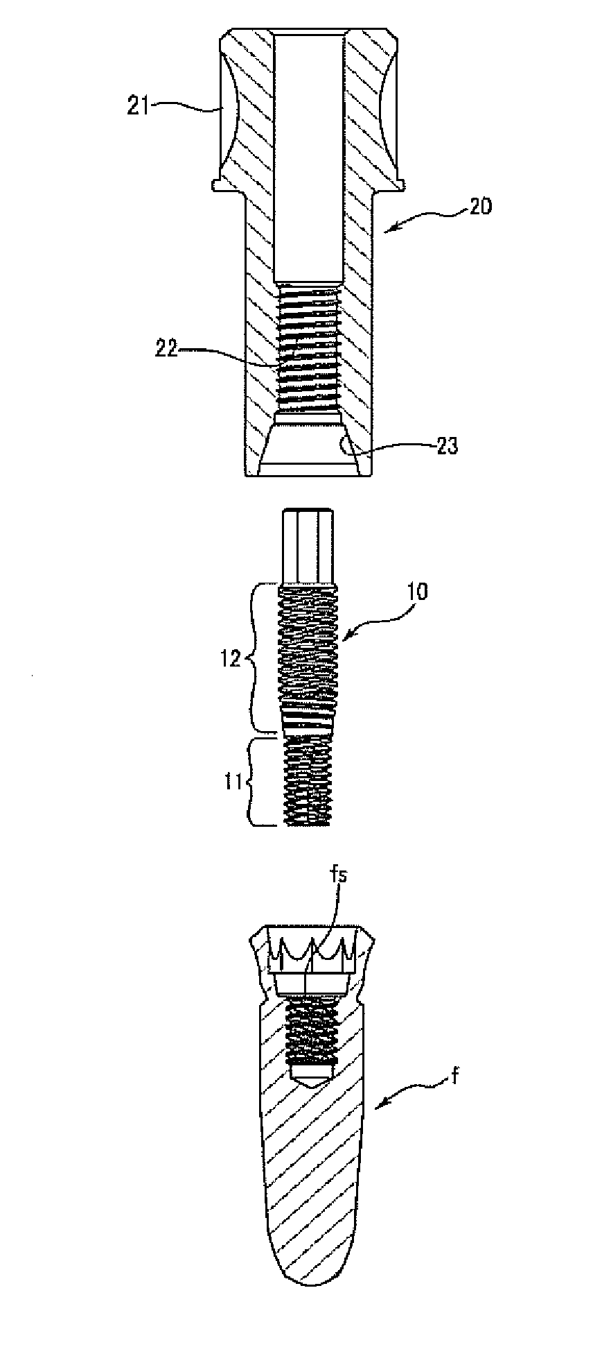
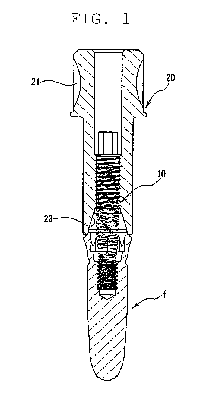
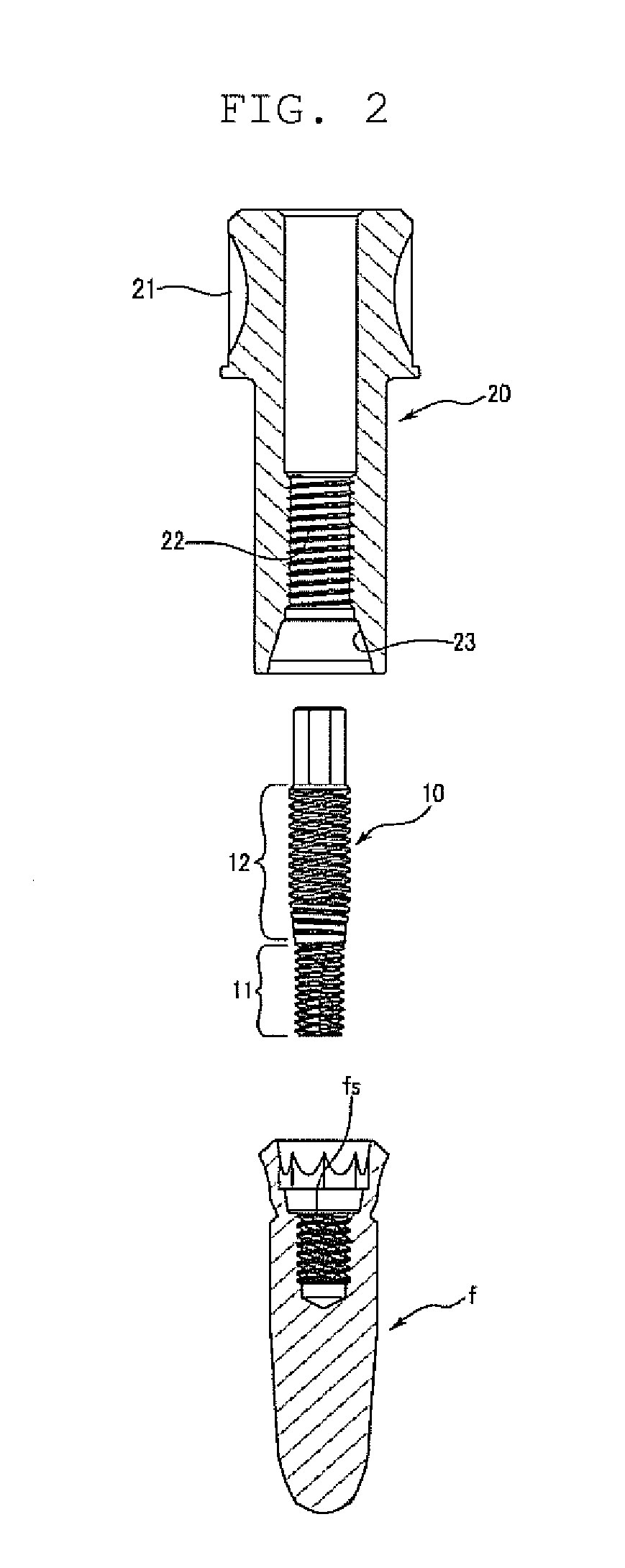
[0033]FIG. 1 is a sectional view illustrating an implant fixture remover in an in-use state according to an embodiment of the invention. FIG. 2 is a sectional view illustrating the implant fixture remover in a separated state shown in FIG. 1. FIG. 3 is a perspective view illustrating a remover screw of the implant fixture remover according to the embodiment of the invention. FIG. 4 is a perspective view illustrating an example of a remover driver of the implant fixture remover according to the embodiment of the invention.

[0034]First, a fixture f separated and removed by a...


PUM


Abstract

An implant fixture remover is provided which includes: a remover screw including a coupling screw portion screwed to a female screw portion of a fixture, and a separating screw portion formed to extend from one end of the coupling screw portion to the outside of the fixture and having a thread formed on the outer circumferential surface thereof; and a remover driver including a separating female screw portion into and to which the separating screw portion of the remover screw is inserted and screwed and in which a thread corresponding to the separating screw portion is formed in the inner circumferential surface thereof, a close coupling portion formed at the lower end of the separating female portion 22 and coming in frictional contact with the upper outer surface of the fixture, and a shank which extends upward from the separating female screw portion and in which a fastening tool is connected to the outer circumferential surface of one end thereof.

Description

CROSS-REFERENCE TO RELATED APPLICATIONS[0001]This application claims the benefit of Korean Patent Application No. 10-2009-0047897 filed with the Korean Intellectual Property Office on May 29, 2009, the disclosure of which is incorporated herein by reference in its entirety.BACKGROUND[0002]1. Field of the Invention[0003]The present invention relates to a medical fixture remover for dental, plastic surgical, and orthopedic applications, which is used to remove a fixture screwed to a human bone and fused to the bone for the reason of failure in bone generation or loss of a bone around an implant, and more particularly, to an implant fixture remover which can separate and remove a fixture from a human bone safely and rapidly with simple and standardized treatment, which can separate the fixture from the human bone safely to enhance the safety of treatment when a fixture connector is damaged with an excessive torque in the course of implanting the fixture and thus cannot be inserted or p...

Claims


Application Information

Patent Timeline
Patent Type & Authority Applications(United States)
IPC IPC(8): A61C13/38A61C3/00
CPCA61C8/0089
Inventor HEO, YOUNG KU
Owner HEO YOUNG KU
Learn More