Relay transmission system, base station, relay station, and method

a transmission system and relay technology, applied in the field of relay transmission systems, can solve the problems of inconvenient mobile terminal use, increased consumption, and inability to reduce power consumption, so as to improve the use efficiency of radio resources and improve the signal quality in uplink.

Inactive Publication Date: 2010-12-02
NTT DOCOMO INC
View PDF9 Cites 70 Cited by
  • Summary
  • Abstract
  • Description
  • Claims
  • Application Information

AI Technical Summary

Benefits of technology

[0014]According to an embodiment of the present invention, it may become possible to improve the signal quality in uplink and the use efficiency of radio resources in ...

Problems solved by technology

However, this method may not be preferable from the viewpoint of reducing the power consumption because the power consumption is likely to increase with the increase of the transmission power.
In particular, this method may not be suitable for a mobile terminal that has only a small battery.
However, this method of increasing the allocation density of the base stations may not be preferable because the cost to build this system becomes high.
This is because when much interference occurs in a specific frequency, c...

Method used


Image

  • Relay transmission system, base station, relay station, and method
  • Relay transmission system, base station, relay station, and method
  • Relay transmission system, base station, relay station, and method

Examples


embodiment 1

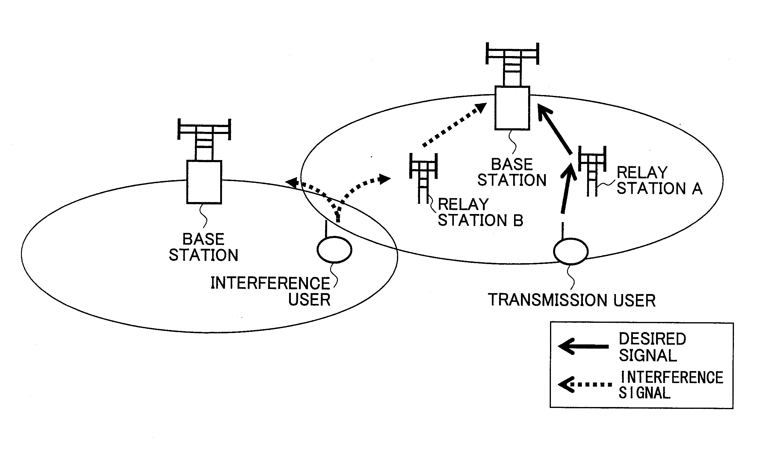
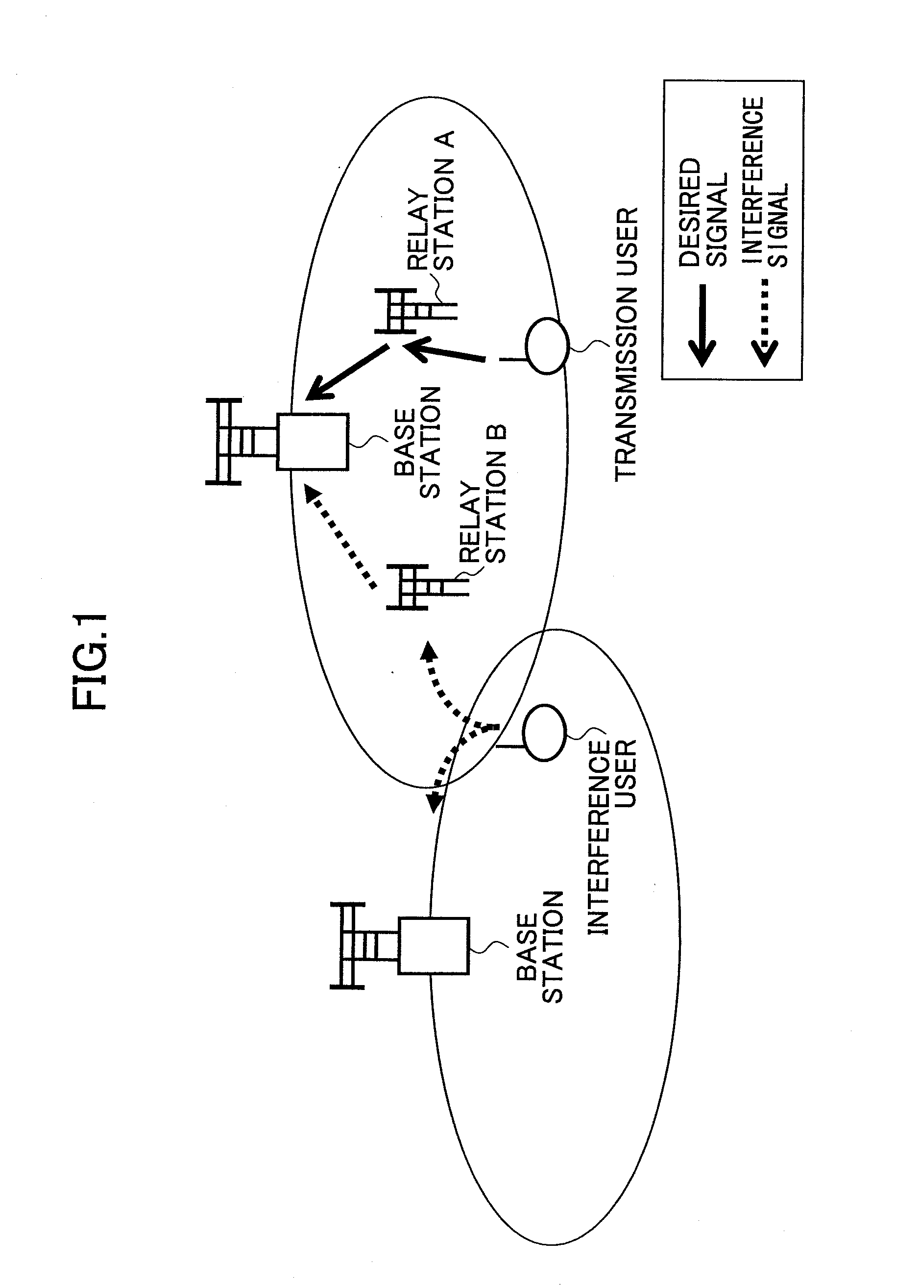
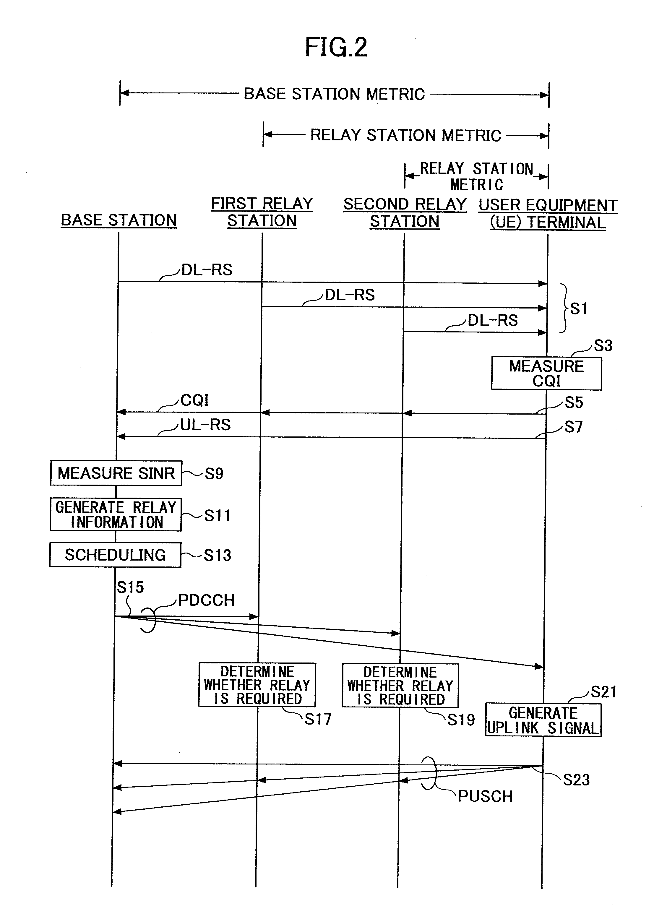
[0050]FIG. 2 is a flowchart showing an exemplary operation according to an embodiment of the present invention. In the following, for explanatory purposes, it is assumed that the relay transmission system includes one base station, a first relay station, a second relay station, and one user equipment (UE) terminal. However, the relay transmission system of the present invention is not limited to this configuration. For example, more or less than two relay stations may be included, and more than one user equipment (UE) terminal may be included in the relay transmission system.

[0051]First, in step S1, Downlink-Reference Signals (DL-RSs) are transmitted from the base station, the first relay station, and the second relay station to the user equipment (UE) terminal in downlink. The Downlink-Reference Signals (DL-RSs) may be pattern signals already known between the transmitting sides and the receiving side. The reference signal may also be referred to as a pilot signal, a training signa...


PUM


Abstract

A base station used in a relay transmission system is disclosed. The base station includes a metric provision unit providing a metric indicating radio propagation conditions of a user equipment terminal; a relay information generation unit generating a relay information for the user equipment terminal based on the metric, the relay information indicating whether an uplink signal is to be transmitted via one or more relay stations; a scheduling unit generating an allocation plan of radio resources based on the relay information; and a control signal transmission unit transmitting a control signal including a scheduling information indicating the allocation plan.

Description

TECHNICAL FIELD[0001]The present invention generally relates to a relay transmission system, and a base station, a relay station, and a method used in the relay transmission system.BACKGROUND ART[0002]In research and development of a mobile communication system, it is important to increase the data rate and improve the use efficiency of radio resources (especially, frequency). When assuming that the required received quality (e.g., received SINR (Signal to Interference plus Noise Ratio)) should be constant, one method of increasing the data rate is to increase the transmission power so as to allow for higher data rates. However, this method may not be preferable from the viewpoint of reducing the power consumption because the power consumption is likely to increase with the increase of the transmission power. In particular, this method may not be suitable for a mobile terminal that has only a small battery. One method of increasing the data rate without changing the maximum transmis...

Claims


Application Information

Patent Timeline
IPC IPC(8): H04B7/14
CPCH04B7/15535H04B7/2606H04W88/08H04W72/08H04W84/047H04W72/54
Inventor HIGUCHI, KENICHI
Owner NTT DOCOMO INC
Why Eureka
Try Eureka