Creation and modification of valid functional design layouts

a functional design and layout technology, applied in the field of system, method and computer program product for modeling and design, can solve problems such as physical impossible or impractical layout, hot circuit, fire hazards,

Active Publication Date: 2010-12-02
ARMSTRONG WORLD IND INC +1
View PDF115 Cites 22 Cited by
  • Summary
  • Abstract
  • Description
  • Claims
  • Application Information

AI Technical Summary

Benefits of technology

[0016]Implementations of the present invention overcome one or more problems in the art with systems, methods, and computer program products configured to capture product information, such as component attributes and parameters, to allow a non-expert user to design a valid functional system layout within a design space. In particular, implementations of the present invention automatically associate product parameters and attributes to both functional and non-functional design components, including all applicable connectors, rules, features, characteristics, and behaviors. Based upon the components and their associated attributes and parameters, implementations of the present invention can automatically apply rules and behaviors to help create a functional system layout in a design space that is physically and functionally valid. Furthermore, implementations of the present invention can optimize the parameters of the functional system layout.
[0018]Additionally, a method in accordance with an implementation of the present invention of automatically configuring user input in a computerized environment to represent a design or layout of components within a design space can involve receiving user input regarding the placement of one or more functional components within a design space. The method can also involve receiving user input regarding the placement of one or more source components within the design space. The method can then involve populating functional system lines with optimized characteristics. The functional system lines can connect the one or more source components and the one or more functional components. The method can further involve receiving additional user input regarding the placement, relocation, or change of one or more of a non-functional design component, a functional component, or a source component within the design space. Additionally, the method can resolve the functional system lines in view of the additional user input.

Problems solved by technology

If the circuit were actually constructed as laid out by the designer, the circuit may be hot and be prone to overload, may be a fire hazard, or may not satisfy the requirements of applicable building codes.
In a situation such as this, however, the builder might indicate to the designer that the layout is physically impossible or impractical, and ask for a redesign.
This, of course, can lead to any number of inefficiencies.
For example, conventional design software is often difficult to use, and heavily dependent on the skill of a user, such that conventional software for laying out functional systems can tend to be accessible primarily or uniquely to “product experts.” In general, a product expert is one who understands the product components, rules, and behaviors in relation to other components (functional and non-functional) in the layout software.
Nevertheless, even product experts can err when attempting to remember all aspects of any particular component, and can fail to remember or identify a component's relationships with respect to other parts of the layout.
One of the problems with many design software programs that can lead to the design of physically or functionally impractical structures, is that many such design problems require some drawing of a space in flat, two-dimensional space.
In addition, neither the three-dimensional rendering nor the two-dimensional drawing views are designed to accommodate necessary modifications to the objects or walls, based on real-world materials, or other important constraints.
Furthermore, the repositioning or replacement of functional components can require changes to the circuits, jumpers, breakers, pumps, vents, and machines supporting the components.
In addition, there are several mistakes that can be made with regard to estimating installation times, as well as time and cost for manual placement, rework, and so forth.
One way that conventional software lends itself to these difficulties is that there it often has inexact or error-prone software relationships between textual versions and graphical oriented versions of components.
The linking between these different databases, however, introduces another area for potential error, and requires additional time for auditing the graphical results against the textual results.
Unfortunately, there is generally not a convenient way for an accurate parts list to be generated automatically from one or more design views.

Method used


Image

  • Creation and modification of valid functional design layouts
  • Creation and modification of valid functional design layouts
  • Creation and modification of valid functional design layouts

Examples


Embodiment Construction

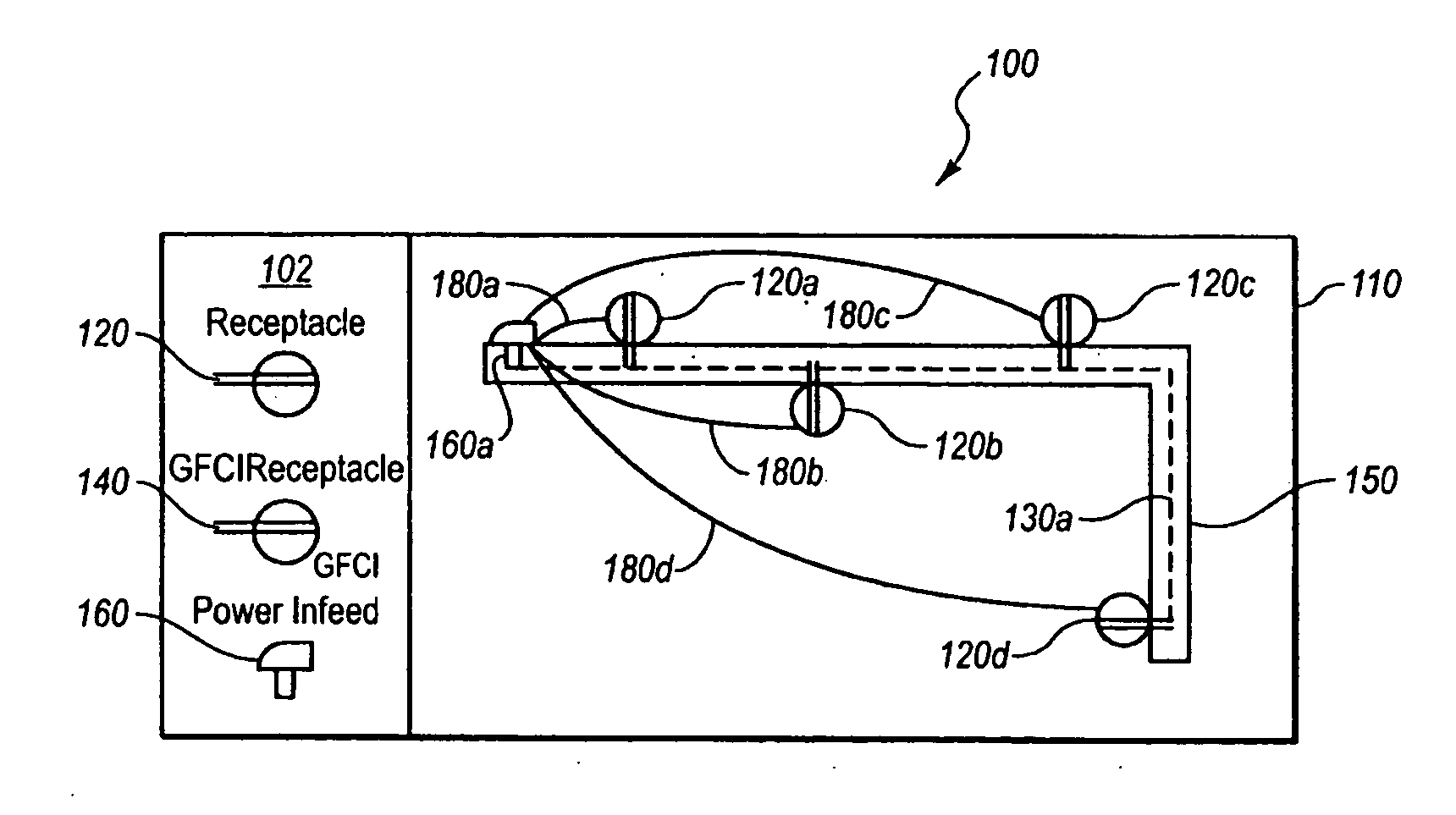
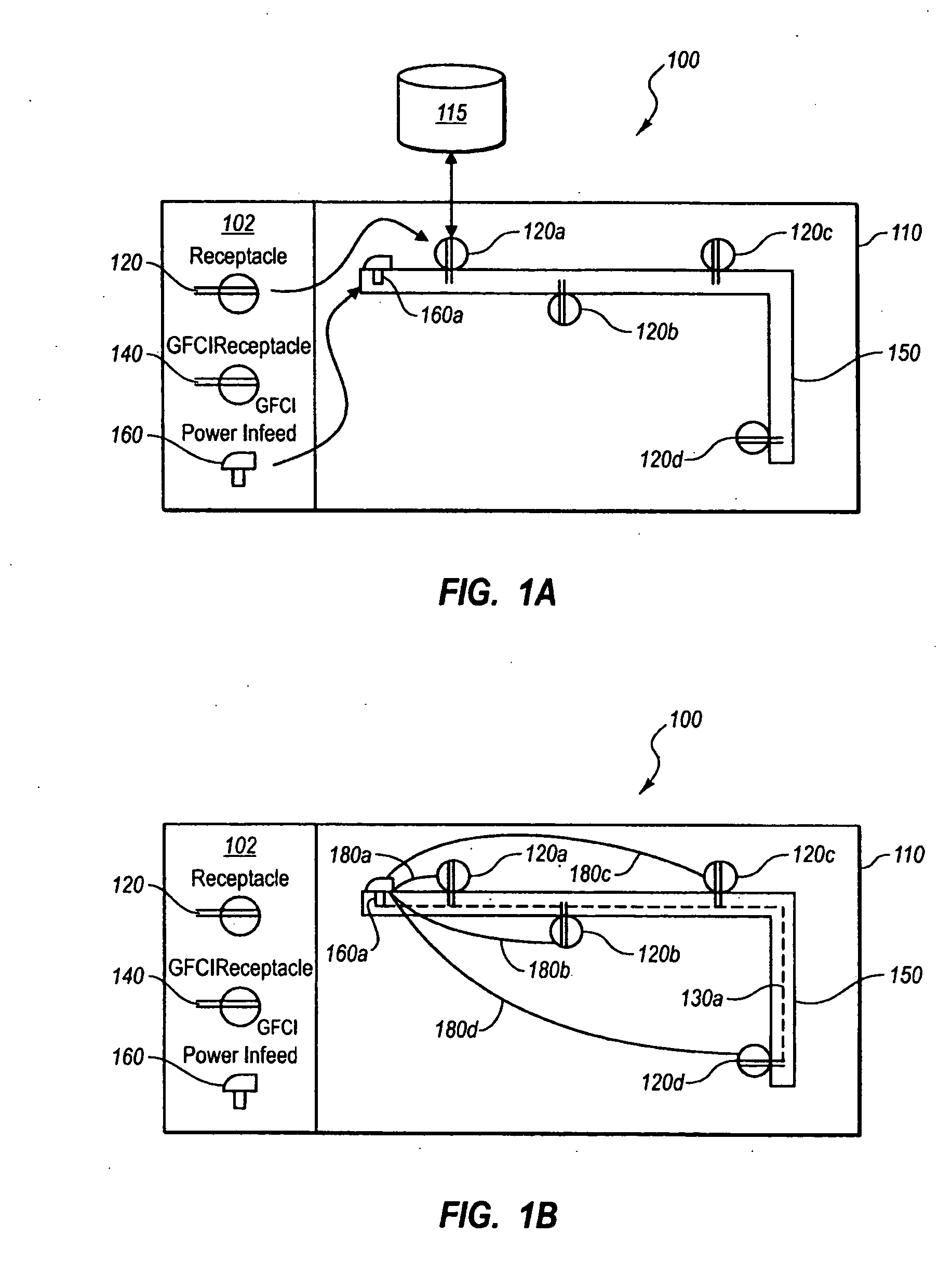
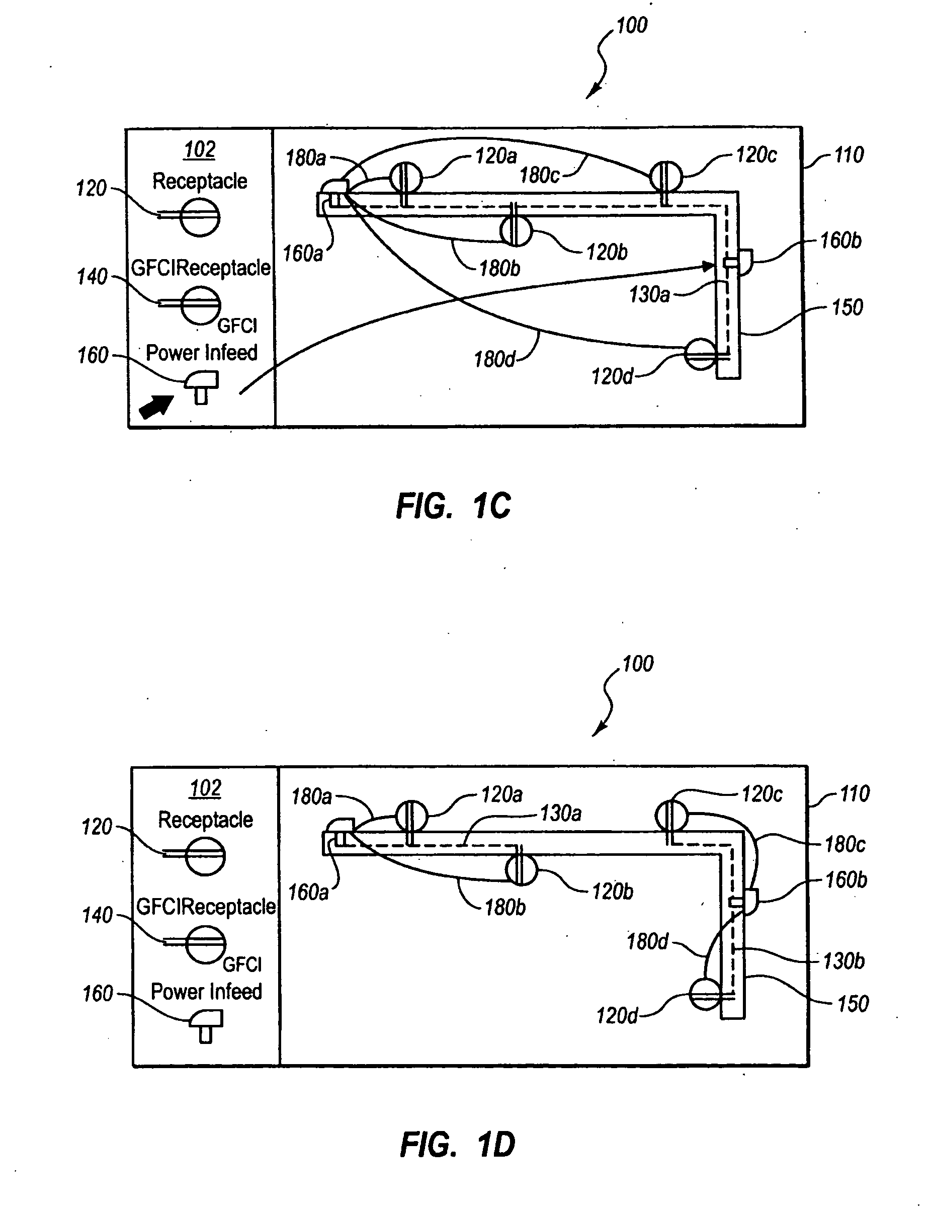
[0034]The present invention extends to systems, methods, and computer program products configured to capture product information, such as component attributes and parameters, to allow a non-expert user to design a valid functional system layout within a design space. In particular, implementations of the present invention automatically associate product parameters and attributes to both functional and non-functional design components, including all applicable connectors, rules, features, characteristics, and behaviors. Based upon the components and their associated attributes and parameters, implementations of the present invention can automatically apply rules and behaviors to help create a functional system layout in a design space that is physically and functionally valid. Furthermore, implementations of the present invention can optimize the parameters of the functional system layout.

[0035]For example, based on the placement of source components (power sources, gas and water val...


PUM


Abstract

A software application can capture product parameters and attributes in order to allow a non-expert user to create a valid functional system layout in a design space. To enable accurate layouts, the software application can automatically apply all applicable components, connectors, rules, attributes, codes, and behaviors to each component / design element in the design space. The intelligent, object-oriented software can apply rules and behaviors automatically, not only providing an accurate, valid layout, but also optimizing the layout. The intelligent, object-oriented software can recognize required changes effected by a user-driven change, and automatically resolve the layout design.

Description

CROSS-REFERENCE TO RELATED APPLICATIONS[0001]The present invention is a U.S. National Stage Application corresponding to PCT / CA2009 / 000190, filed on Feb. 13, 2009, entitled “Creation and Modification of Valid Functional Design Layouts,” which claims the benefit of priority to U.S. Provisional Patent Application No. 61 / 028,409, filed on Feb. 13, 2008, entitled “Automated Layout of Electrical Components and Wiring Intent in Design Software.”[0002]The present invention is also a continuation-in-part of U.S. patent application Ser. No. 11 / 204,421, filed on Aug. 16, 2005, entitled “Capturing a User's Intent in Design Software”, which claims the benefit of priority to U.S. Patent Provisional Application 60 / 602,233, filed on Aug. 17, 2004, now abandoned, entitled “Method and Apparatus for the Selection, Organization and Configuration of Products through Object Oriented Design Intent.” The entire content of each of the aforementioned patent applications is incorporated herein by reference.B...

Claims


Application Information

Patent Timeline
Patent Type & Authority Applications(United States)
IPC IPC(8): G06F3/048G06F17/50G06N5/02G06T17/40
CPCG06F17/5004G06T19/00G06N5/02G06F2217/06G06F30/13G06F2111/04
Inventor LOBERG, BARRIE A.BODEN, DALE
Owner ARMSTRONG WORLD IND INC
Why Eureka
Try Eureka