Cleaner head

Active Publication Date: 2010-12-09
DYSON TECH LTD
View PDF32 Cites 31 Cited by
  • Summary
  • Abstract
  • Description
  • Claims
  • Application Information

AI Technical Summary

Benefits of technology

[0020]In a third aspect, the present invention provides a cleaner head for a surface treating appliance, the cleaner head comprising a housing and apparatus as aforementioned. The cleaner head preferably comprises a plurality of support members, preferably in the form of rolling elements such as wheels or rollers, for supporting the cleaner head on a surface to be cleaned. Preferably, the first agitating means does not protrude beneath a plane extending between the lowermost extremities of the supp

Problems solved by technology

This can impair the cleaning performance on the cleaner head on such floor surfaces, as the sweeping action

Method used


Image

  • Cleaner head
  • Cleaner head
  • Cleaner head

Examples


Embodiment Construction

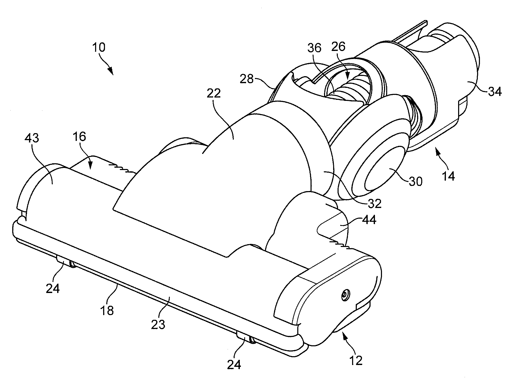
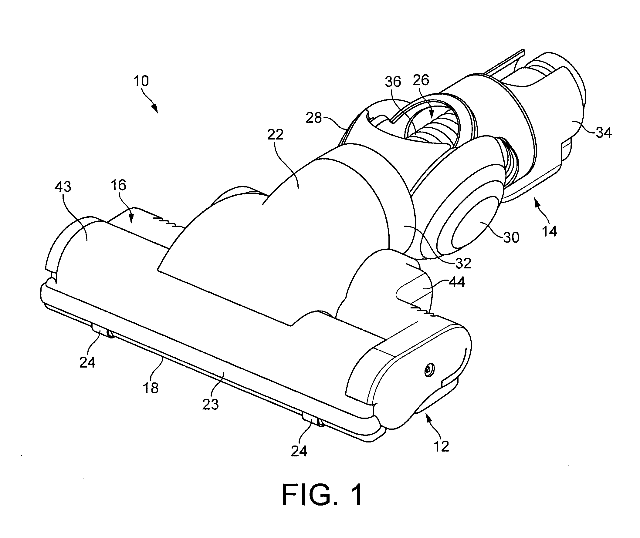
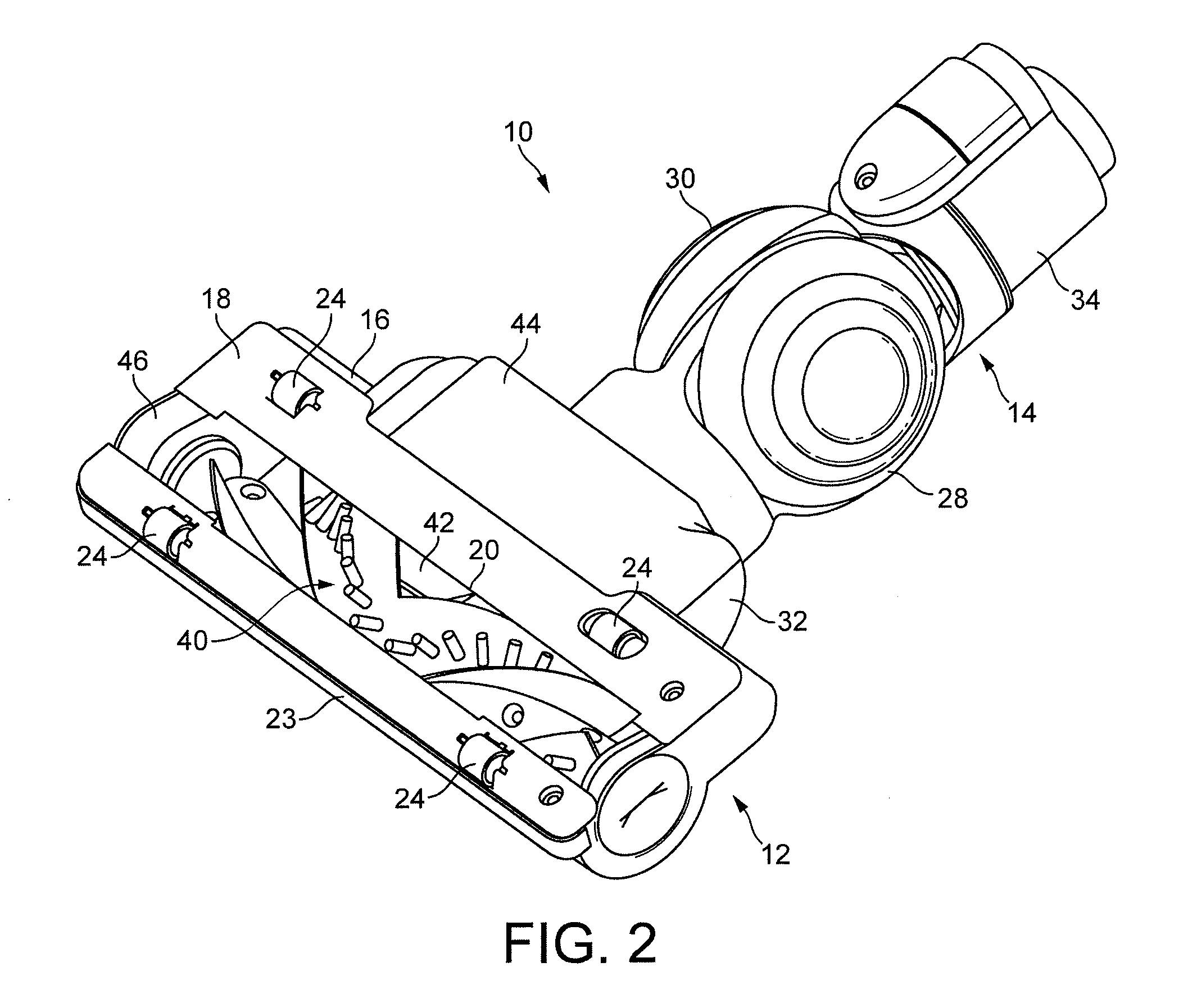
[0036]With reference first to FIGS. 1 to 3, a floor tool 10 comprises a cleaner head 12 rotatably attached to a coupling 14. The free end of the coupling 14 is attachable to a wand, hose or other such duct of a cleaning appliance (not shown). The cleaner head 12 comprises a housing 16 and a lower plate, or sole plate 18, comprising a suction opening 20 through which a dirt-bearing fluid flow enters the cleaner head 12. The housing 16 defines a suction passage extending from the suction opening 20 to an outlet duct 22 located at the rear of the housing 16. The housing 16 preferably comprises a front bumper 23. The sole plate 18 comprises a plurality of support members 24 in the form of rolling elements mounted within recessed portions of the sole plate 18 for supporting the cleaner head 12 on a floor surface. With reference to FIGS. 7 and 8, the support members 24 are preferably arranged to support the sole plate 18 above the floor surface when the cleaner head 12 is located on a har...


PUM


Abstract

A cleaner head for a surface treating appliance includes a housing and a rotatable brush bar located within the housing. The brush bar includes a first plurality of bristles and a second plurality of bristles which protrude radially outwardly beyond the first plurality of bristles. The second plurality of bristles has a surface resistivity in the range from 1×10⁻⁵ to 1×10¹² Ω/sq so that static electricity residing on a floor surface to be cleaned is discharged upon contact with the conductive bristles.

Description

REFERENCE TO RELATED APPLICATIONS[0001]This application claims the priority of United Kingdom Application No. 0909896.3, filed Jun. 9, 2009, the entire contents of which are incorporated herein by reference.FIELD OF THE INVENTION[0002]The present invention relates to agitating apparatus for a surface treating appliance, and to a cleaner head for a surface treating appliance. In its preferred embodiment, the present invention relates to a cleaner head for a vacuum cleaning appliance.BACKGROUND OF THE INVENTION[0003]A vacuum cleaner typically comprises a main body containing dirt and dust separating apparatus, a cleaner head connected to the main body and having a suction opening, and a motor-driven fan unit for drawing dirt-bearing air through the suction opening. The dirt-bearing air is conveyed to the separating apparatus so that dirt and dust can be separated from the air before the air is expelled to the atmosphere.[0004]The suction opening is directed downwardly to face the floo...

Claims


Application Information

Patent Timeline
IPC IPC(8): A47L9/04
CPCA46B13/006A47L9/0477A46B2200/3033A46B13/02A47L9/02A47L9/04
Inventor FOLLOWS, THOMAS JAMES DUNNINGCOURTNEY, STEPHEN BENJAMIN
Owner DYSON TECH LTD
Why Eureka
Try Eureka