Express-registering regions of the body

a technology of express registration and body, applied in the field of determining the region of the body, can solve the problems of time-consuming and laborious input, and parts of the patient's body cannot be clearly integrated into the model data s

Active Publication Date: 2010-12-09
BRAINLAB
View PDF2 Cites 11 Cited by
  • Summary
  • Abstract
  • Description
  • Claims
  • Application Information

AI Technical Summary

Benefits of technology

[0032]It is also possible within the framework of this invention to determine an anterior-posterior direction of the anatomical part of the body. An anterior-posterior direction is in particular understood to mean a direction which runs perpendicular to a frontal plane of the patient's body. If the anatomical part of the body represents a bone in a limb of the patient's body, then the anterior-posterior direction also runs perpendicular to the longitudinal axis of this bone, if the longitudinal axis runs in the proximal-distal direction. The clear assignment of the positional distribution of the patient landmarks to a region of the body, in particular to a right-hand or left-hand side of the body, can also be used—with the aid of other geometric considerations—to determine an anterior-posterior direction of the anatomical part of the body. This directional determination can be important in the surgical navigation method, in order for example to be able to navigate particular instruments relative to the anatomical part of the body.

Problems solved by technology

A problem exists here, in that a right lower leg bone and a left lower leg bone can for example exhibit a congruent shape and / or view, depending on the position of the observer and / or the perspective from which the bone is observed.
This leads to a problem in assigning the corresponding part of the patient's body to the corresponding parts of the body in the model data set of the patient's body which is stored before the operation.
In particular, the part of the patient's body can no longer be clearly incorporated into the model data set.
This can however result in errors, which can for example be based on an incorrect input by the user.
Inputting also takes time.

Method used


Image

  • Express-registering regions of the body
  • Express-registering regions of the body
  • Express-registering regions of the body

Examples


Embodiment Construction

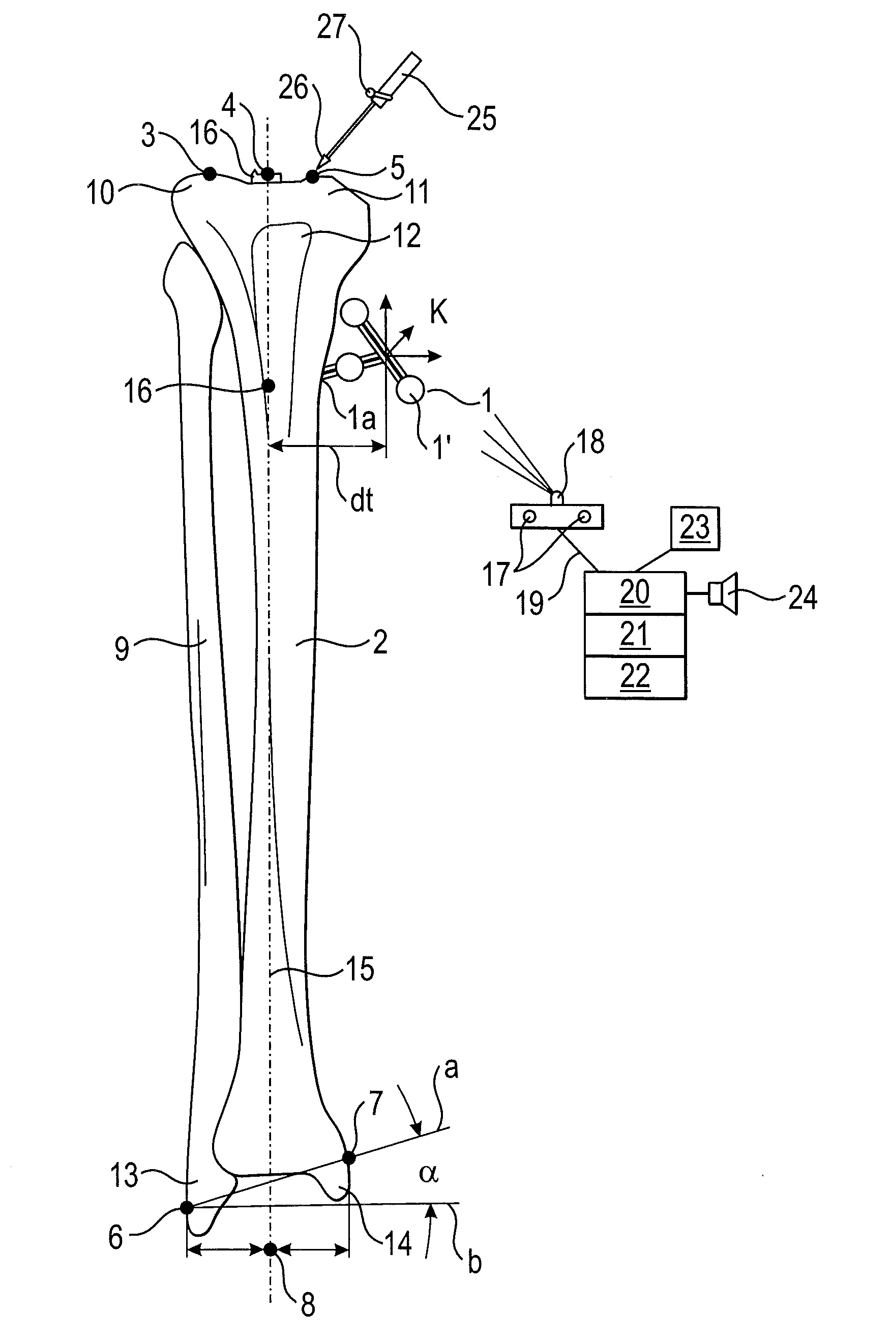
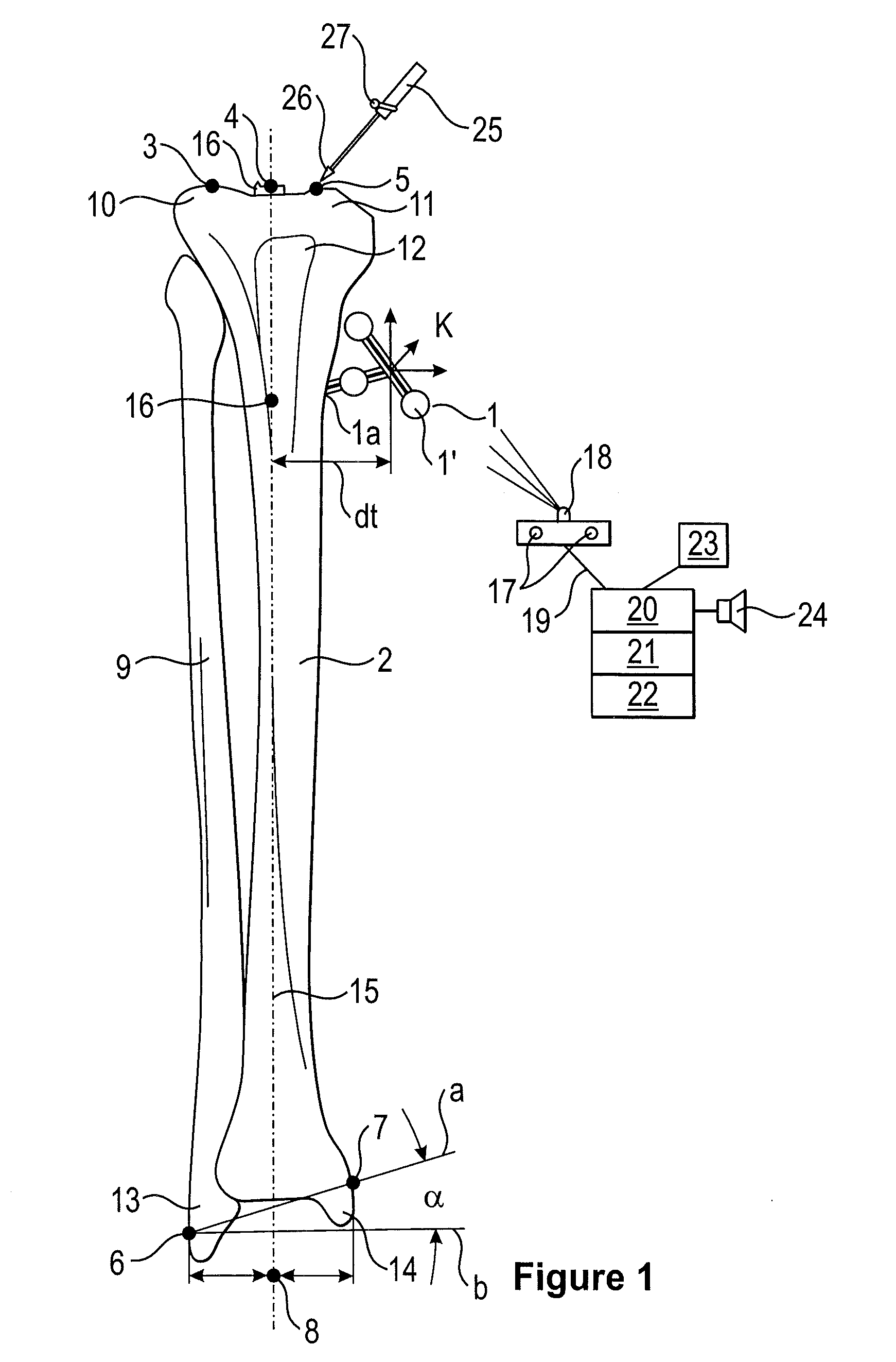
[0052]The reference sign X is used in the following as an abbreviation for the set of reference signs 1a, 3, 4, 5, 6, 7. The reference sign Y is used in the following as an abbreviation for the set of reference signs 17, 18, 20, 21, 22, 23.

[0053]FIG. 1 shows the position of the patient landmarks X on a tibia and a fibula, and the tibial axis (longitudinal axis) being ascertained with the aid of a surgical navigation system. A reference star 1 is attached on a tibia 2 in the reference point 1a in the region of the tubercle 12 of the tibia. It is also possible to dispense with the reference star 1 if the reference point 1a is registered and / or established with the aid of a pointer 25 at the beginning of the method or if at least one patient landmark X does not lie in a common plane with the other patient landmarks X. Registering comprises assigning the reference point 1a in the patient data set to the corresponding co-ordinates in the model data set. The surgeon can tap the patient la...


PUM


Abstract

The present invention relates to a method for determining the region of the body in which an anatomical part of the body is situated, said method including the following steps:
    • anatomical point data is provided which includes information concerning a spatial pattern of positions of patient landmarks of a part of a patient's body which corresponds to the anatomical part of the body;
    • landmark data is provided which includes information concerning a spatial pattern of positions of model landmarks of a model of the anatomical part of a patient's body;
wherein, assuming that
  • the patient landmarks represent the same landmarks as the model landmarks,
  • the region of the body in which the part of the patient's body is situated is determined on the basis of the landmark data and the anatomical point data.

    Description

    RELATED APPLICATION DATA[0001]This application claims the priority of U.S. Provisional Application No. 61 / 233,520, filed on Aug. 13, 2009, which is hereby incorporated in its entirety by reference.FIELD OF THE INVENTION[0002]The present invention relates to a method for determining the region of the body, in particular a right-hand or left-hand side of the body, in and / or on which an anatomical part of the body—for example, a lower leg bone (in particular, a tibia and / or fibula)—is situated which is in particular formed to be substantially symmetrical to a part of the body which lies on the other side and / or in another region of the body.BACKGROUND OF THE INVENTION[0003]In surgical navigation methods (IGS=image-guided surgery), the surgeon regularly needs to assign parts of the body, which for example are arranged symmetrically on different sides of the body, to the corresponding side. A problem exists here, in that a right lower leg bone and a left lower leg bone can for example ex...

    Claims


    Application Information

    Patent Timeline
    Patent Type & Authority Applications(United States)
    IPC IPC(8): A61B19/00
    CPCA61B5/4504A61B5/103A61B2019/505A61B2019/5268A61B19/5244A61B5/6878A61B2019/5255A61B34/20A61B2034/105A61B2034/2055A61B2034/2068
    Inventor NEUBAUER, TIMOUHING, FRANK
    Owner BRAINLAB
    Why Eureka
    Try Eureka