
Floating cut-off bar for a mold box

Active Publication Date: 2010-12-09
KEYSTONE RETAINING WALL SYST
View PDF34 Cites 37 Cited by
  • Summary
  • Abstract
  • Description
  • Claims
  • Application Information

AI Technical Summary

Benefits of technology

[0014]The invention comprises a cut-off bar that is not rigidly attached to the feed drawer and that can remove and / or redistribute varying amounts of mix material as necessary to all portions of the mold box cavity for more precise and accurate control to enhance the structural strength and integrity of the block being produced and thus the structure being built with the block.

Problems solved by technology

Since the cut-off bar follows the horizontal path of the feed drawer there is not a suitable means for distributing and leaving additional material in one portion of the mold cavity or less material in another portion of the mold cavity as may be necessary / optimal depending upon the shape and size of the block being produced.
If the mold cavities and moveable sideliners are aligned in parallel with the path of travel, then the rigid cut-off bar can be shaped to deposit the correct proportion of material over the area of need, but when the cavities are perpendicular to the feed drawer, there is currently no effective means to accomplish the correct distribution.
This produces an uneven range of density along the gradient where the material was compressed by the stripper shoe head assembly, thus the structural integrity and strength of the block may be compromised which could additionally compromise the structural integrity and strength of any structure made from the blocks.
In addition, where the block is over compressed, the material may expand (rebound) when released from the mold cavity and the planer surfaces may tear as a function of this rebound effect.
Current feed drawer and cut-off bar distribution techniques do not allow for additional material to be distributed to an area of the mold cavity that may require additional material during compression.

Method used


Image

  • Floating cut-off bar for a mold box
  • Floating cut-off bar for a mold box
  • Floating cut-off bar for a mold box

Examples


Embodiment Construction

[0039]The blocks produced from this invention may be made of a rugged, weather resistant material, such as concrete. Other suitable materials include plastic, fiberglass, composite materials, steel, other metals and any other materials suitable for use in molding wall blocks. The surface of the blocks may be smooth or may have a roughened appearance, such as that of natural stone. The blocks are formed in a mold and various textures can be formed on the surface, as is known in the art. It should be appreciated that the invention is equally applicable to blocks of all sizes including those whose faces are either larger or smaller than the ones referenced herein

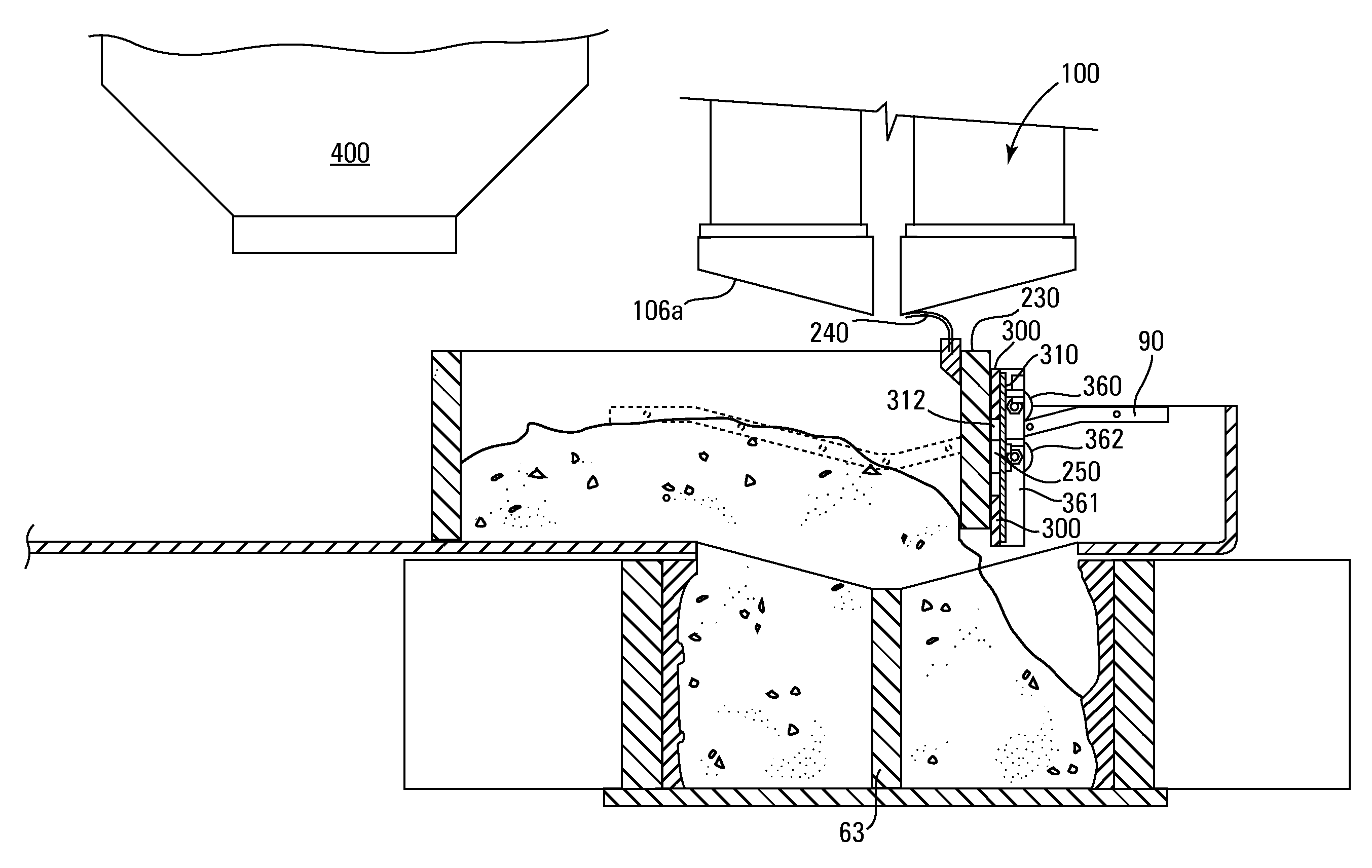
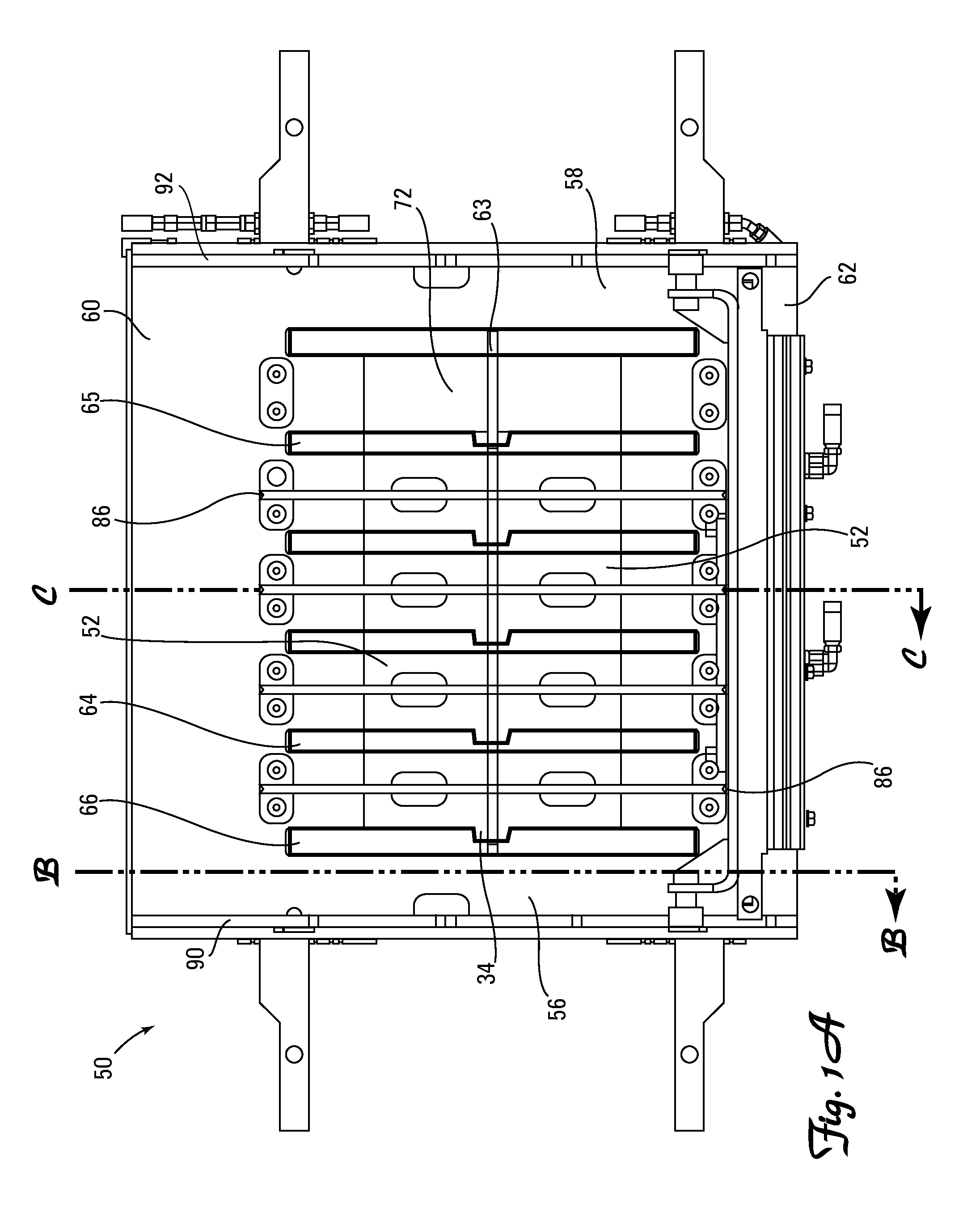
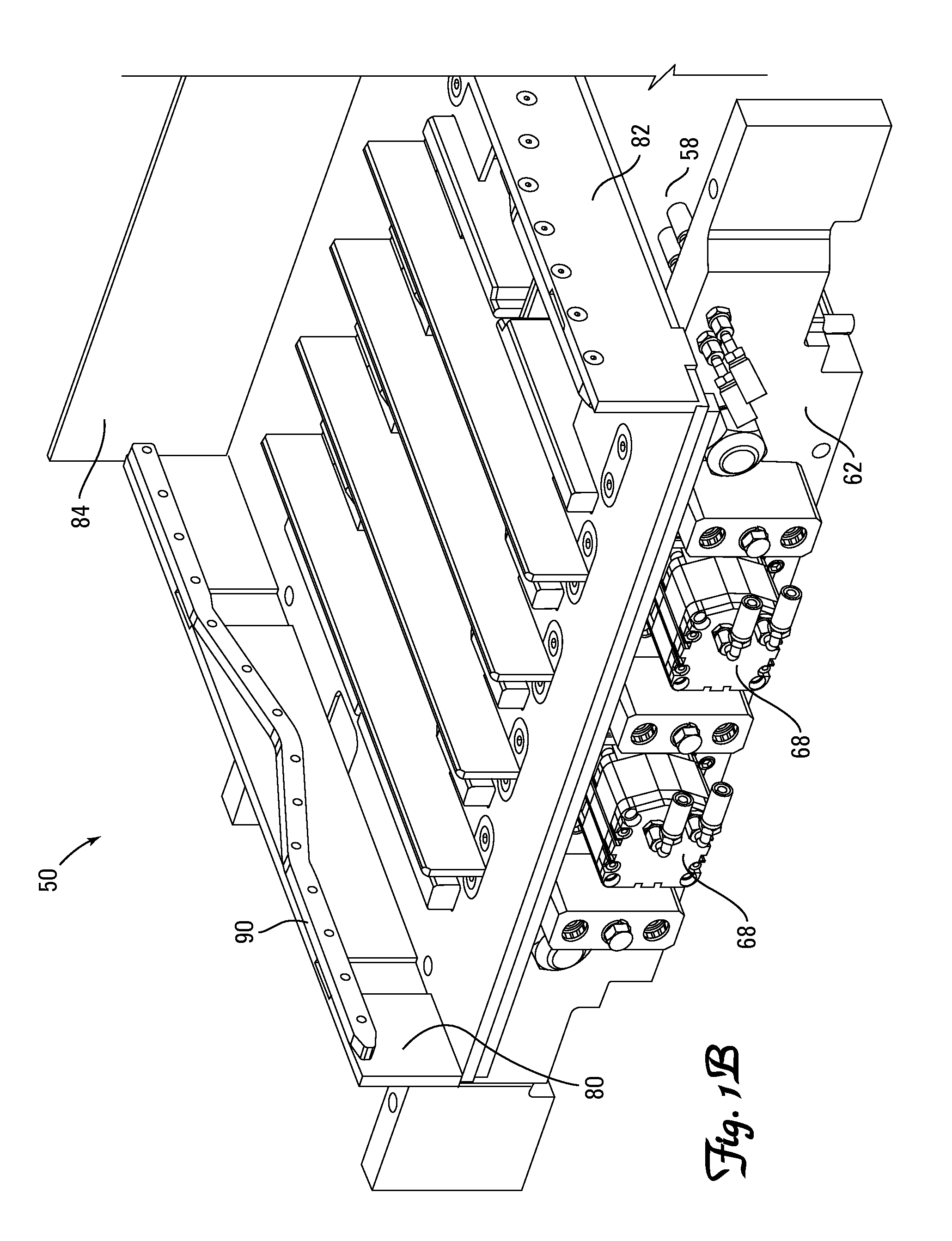
[0040]In accordance with an embodiment of the present invention retaining wall blocks are formed in mold box assemblies as described below. The mold box assemblies have multiple mold cavities and the blocks are formed with a first side surface resting on the production pallet and the second side surface oriented at the top of t...


PUM

PropertyMeasurementUnit
Angleaaaaaaaaaa
Angleaaaaaaaaaa
Angleaaaaaaaaaa

Abstract

A floating cut-off bar coupled to a feed drawer whereby a mechanism allows the floating cut-off bar to engage the specified contour of side rails and a division plate in a mold box assembly and aid in material distribution by screeding excess material and delivering additional material to areas of the mold box as necessary and method of making wall blocks therefrom. The specified contour of the side rails and optionally division plate is designed to optimally deliver material to achieve a specified uniform density of the block produced for greater structural integrity, strength and durability of the block.

Description

[0001]This application claims the benefit of U.S. Provisional Application No. 61 / 183,721, filed Jun. 3, 2009, entitled “Floating Cut-Off Bar for a Mold Box”, the contents of which are hereby incorporated by reference herein.[0002]The contents of U.S. Provisional Application No. 61 / 183,611, filed Jun. 3, 2009, entitled “Floating Cut-Off Bar and Method of Use Thereof', and U.S. application Ser. No. 12 / 580,368, filed Oct. 16, 2009, entitled “Floating Cut-Off Bar and Method of Use Thereof”, are hereby incorporated by reference herein.FIELD OF THE INVENTION[0003]The present invention relates generally to the production of concrete wall blocks with equal material distribution throughout the mold cavity of the block to produce structurally durable, strong and sound blocks. More particularly the invention relates to producing wall blocks with the use of a floating cut-off bar that is separated but movably coupled to a feed drawer for more equal distribution of the mix material dispersed to ...

Claims


Application Information

Patent Timeline
IPC IPC(8): B29C39/24B29C39/02
CPCB28B7/0041B28B7/0064B30B15/304B28B13/0295B28B15/005B28B13/023
Inventor LACROIX, DAVID M.MACDONALD, ROBERT A.
Owner KEYSTONE RETAINING WALL SYST
Features
  • Generate Ideas
  • Intellectual Property
  • Life Sciences
  • Materials
  • Tech Scout
  • Unparalleled Data Quality
  • Higher Quality Content
  • 60% Fewer Hallucinations
Learn More