Lighting fixture with low voltage transformer and self-powered switching system

a low-voltage transformer and switching system technology, applied in the integration of power network operation systems, generators/motors, pulse techniques, etc., can solve the problems of cable kinks, tangles or binds, difficulty in drilling holes and mounting switches and junction boxes,

Inactive Publication Date: 2010-12-09
FACE BRADBURY R +1
View PDF13 Cites 82 Cited by
  • Summary
  • Abstract
  • Description
  • Claims
  • Application Information

AI Technical Summary

Benefits of technology

[0032]In the present invention a self-powered switch initiation system uses an electroactive element to develop an oscillating electrical signal. The accompanying circuitry is designed to work with that signal and generate a coded RF transmission. The codes are preferably a 32-bit binary code comprising a unique (i.e., one of 224 to 230 combinations) transmitter identification code and a function code. To further enhance the system, the system uses a repeater / transceiver system to increase transmission range and reliability of receipt of transmitted signals. The codes sent by the transmitter are modified and rebroadcast by the repeater(s). The response action by the receiver and repeaters to codes either from a transmitter or another repeater depends on the nature of the received code. The nature of the information contained in the code e.g., identification, function and source, is further described. Repeaters also use a poling / initialization routine to assign times slots to each repeater to prevent interference between repeaters.
[0035]Preferably the receiver has an output of at least three activation signals corresponding to “ALL OFF”, “ALL ON”, and “HALF ON” which signals are directed through one or more relay controllers to the bifurcated / three-way output(s) of the switched relay. Alternately, the receiver may have multiple output ports, which are selectable dependent upon the device to be controlled. The receiver is programmable to control multiple devices, i.e., the receiver is programmed to control many different devices, and the programming varies dependent upon the operating mode of the device to be controlled. Each of the output ports of the receiver has access to different programs / operating modes within the receiver. Therefor, attaching a device to defined output ports allows those devices to be controlled with the appropriate programming / control modes from a single receiver.
[0037]It is another object of the present invention to provide a device of the character described in which transmitters may be installed without necessitating additional wiring.
[0038]It is another object of the present invention to provide a device of the character described in which transmitters may be installed without cutting holes into the building structure.
[0039]It is another object of the present invention to provide a device of the character described in which transmitters do not require external electrical input such as 120 or 220VAC or batteries.
[0045]It is another object of the present invention to provide a device of the character described which uses a repeater system for extending the range of transmission and reception reliability between transmitters and receivers.

Problems solved by technology

Drilling holes and mounting switches and junction boxes can be difficult and time consuming.
Though simple in theory, getting cable to cooperate can be difficult and time consuming.
Cable often kinks, tangles or binds while pulling, and needs to be straightened out somewhere along the run.
A problem with conventional wall switches is that extensive wiring must be run both from the switch boxes to the lights and from the switch boxes to the power source in the service panels.
Another problem with conventional wall switches is that additional wiring must be run for lights controlled by more than one switch.
Another problem with conventional wall switches is that the voltage lines are present as an input to and an output from the switch.
Another problem with conventional wall switches is the cost associated with initial installation of wire to, from and between switches.
Another problem with conventional wall switches is the cost and inconvenience associated with remodeling, relocating or rewiring existing switches.
A problem with conventional RF transmitters is that they require an external power source such as high voltage AC power or batteries.
Another problem with conventional battery-powered RF transmitters is the cost and inconvenience associated with replacement of batteries.
Another problem with conventional AC-powered RF transmitters is the difficulty when remodeling in rewiring or relocating a wall transmitter.
Another problem with conventional RF switching systems is that a pair comprising a transmitter and receiver must generally be purchased together.
Another problem with conventional RF switching systems is that transmitters may inadvertently activate incorrect receivers.
Another problem with conventional RF switching systems is that receivers may accept an activation signal from only one transmitter.
Another problem with conventional RF switching systems is that transmitters may activate only one receiver.
Another problem with conventional RF switching systems is that multiple signals from transmitters and / or repeaters may inadvertently activate or deactivate a receiver switching mechanism.
Another problem with conventional RF switching systems is that receivers may have their reception blocked by building obstacles.
Another problem with conventional RF switching systems is that multiple types of receivers are necessary depending on the type of input voltage that is available.
Another problem with conventional RF switching systems is that receivers are not isolated from the voltage passed through the relay they control.

Method used


Image

  • Lighting fixture with low voltage transformer and self-powered switching system
  • Lighting fixture with low voltage transformer and self-powered switching system
  • Lighting fixture with low voltage transformer and self-powered switching system

Examples


Embodiment Construction

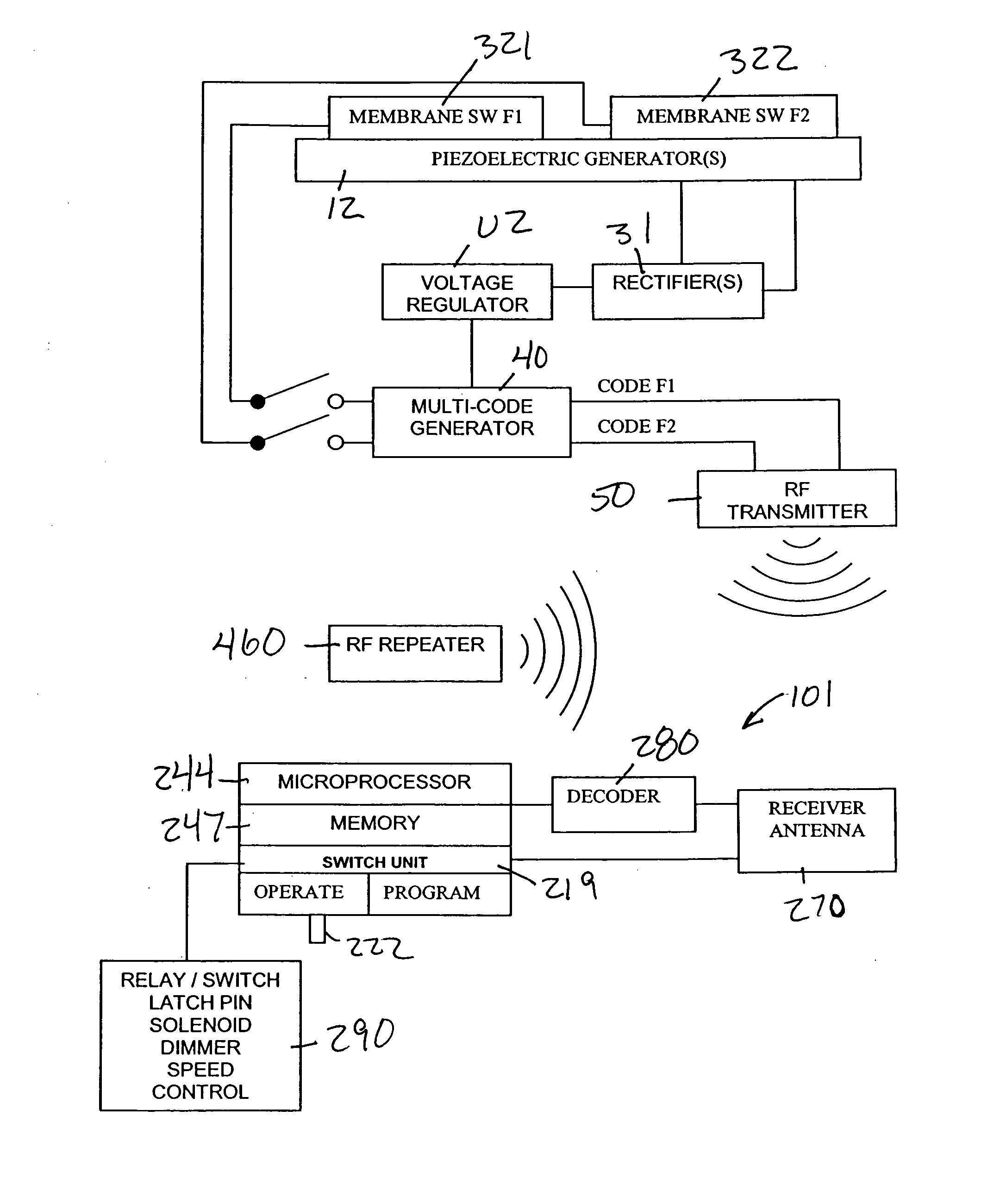
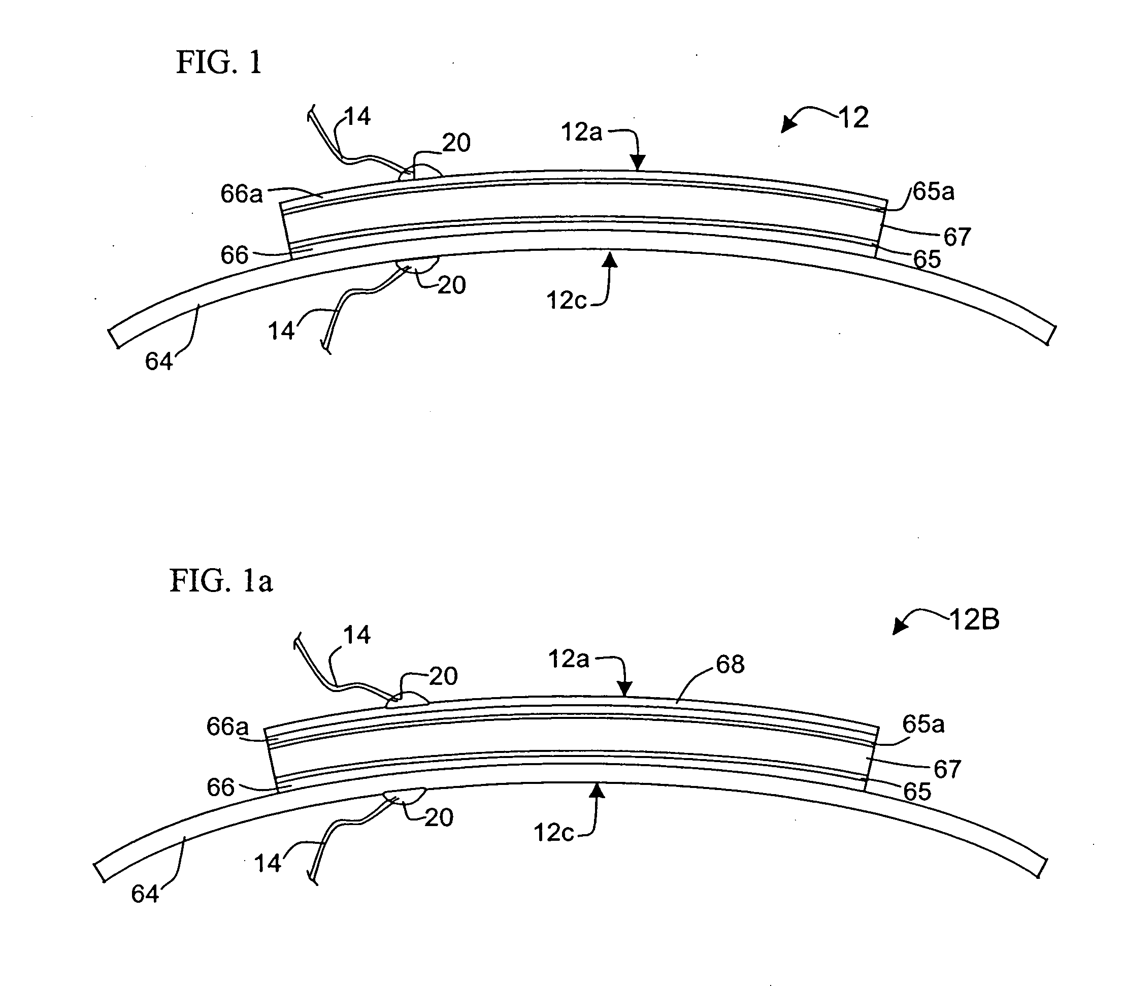
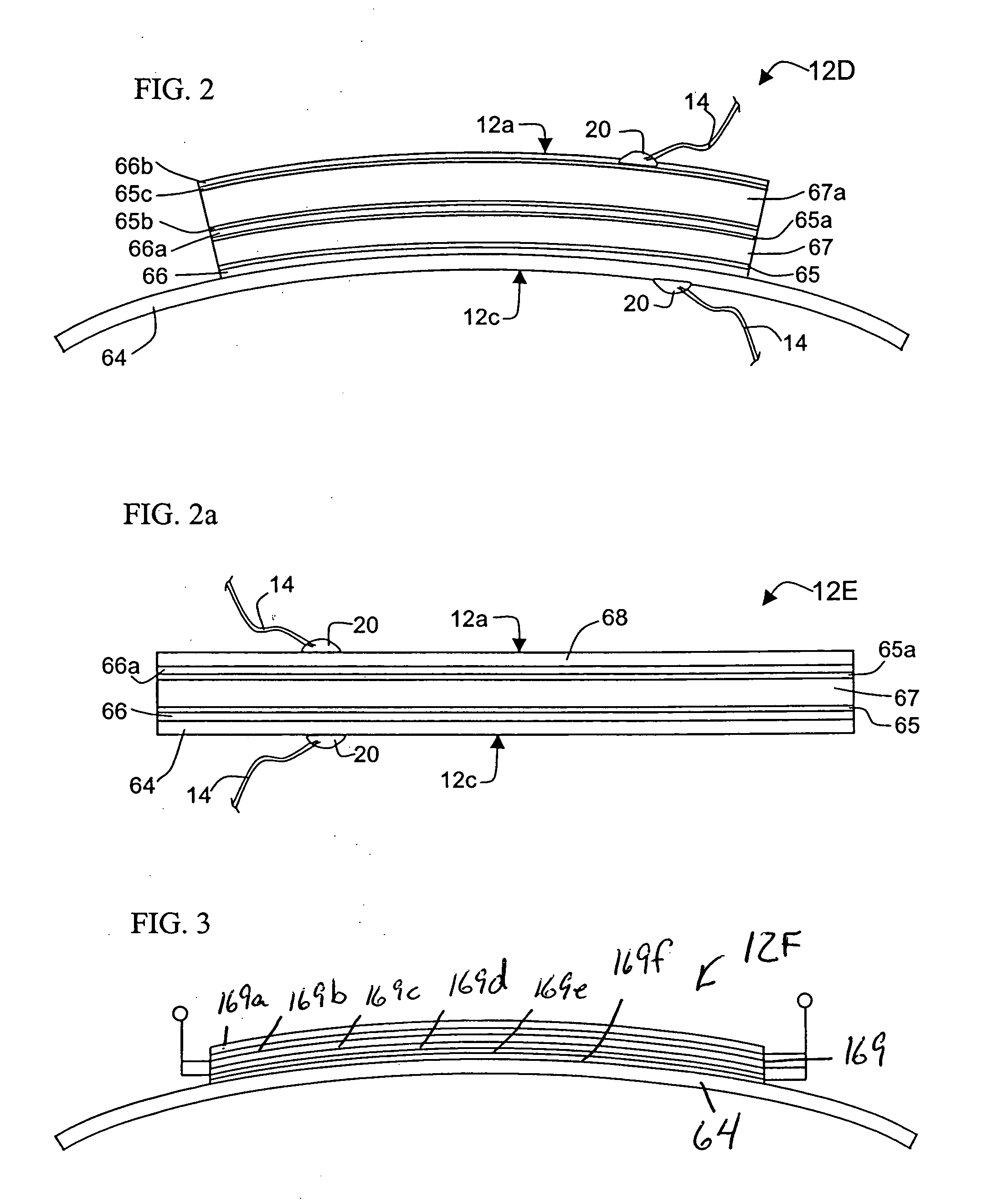
Electroactive Generator

[0086]Piezoelectric and electrostrictive materials (generally called “electroactive” devices herein) develop an electric field when placed under stress or strain. The electric field developed by a piezoelectric or electrostrictive material is a function of the applied force and displacement causing the mechanical stress or strain. Conversely, electroactive devices undergo dimensional changes in an applied electric field. The dimensional change (i.e., expansion or contraction) of an electroactive element is a function of the applied electric field. Electroactive devices are commonly used as drivers, or “actuators” due to their propensity to deform under such electric fields. These electroactive devices when used as transducers or generators also have varying capacities to generate an electric field in response to a deformation caused by an applied force. In such cases they behave as electrical generators.

[0087]Electroactive devices include direct and indirect m...


PUM


Abstract

A self-powered switching system using electromechanical generators generates power for activation of a latching relay, switch, solenoid or latch pin. The electromechanical generators comprise electroactive elements that may be mechanically actuated to generate electrical power. The associated signal generation circuitry may be coupled to a transmitter for sending RF signals to a receiver which actuates the latching relay. The use of mechanically activated membrane switches on the deflector or on a keypad allows multiple code sequences to be generated for activating electrical appliances. The system also uses a communications protocol allowing the receivers to respond to signals from transmitters and / or repeaters. The use of one or more repeaters also increases the reliability of the system as well as extending its effective transmission range. The receivers use low DC voltage (which may be stepped down from the high switched voltage) to generate switching signals to control a low voltage controller for control of high or low voltage switching relays.

Description

[0001]This application claims priority to PCT Application Serial No. PCT / US08 / 06679, filed on May 27, 2008, which claims the benefit of U.S. Provisional Patent Application Ser. No. 60 / 931,572 filed May 24, 2007 entitled “Lighting Fixture with Low Voltage Transformer & Self-Powered Switching System.BACKGROUND OF THE INVENTION[0002]1. Field of the Invention[0003]The present invention relates to light fixture having a transformed low voltage receptacle used for powering among other things an electronically coded switching system. More particularly, the present invention relates to a self-powered device that generates one or more activation signals for a low voltage switch. Electrical power in a wireless transmitter is generated by deforming a piezoelectric element while pressing the face plate or individual membrane switches on the face plate. When the face plate is depressed, the electrical power may then be used to power a RF transmitter to send one or more electronic codes to actuat...

Claims


Application Information

Patent Timeline
Patent Type & Authority Applications(United States)
IPC IPC(8): H02J17/00
CPCH01H2239/076Y04S20/227H01H2300/032H01L41/1134H02J13/0075H02N2/18H03K17/964H03K17/965H05B37/0272Y02B70/3283Y02B90/224Y02B90/2653Y04S20/14Y04S20/246Y04S40/126Y02B70/3241H01H2300/03H01H2201/02H05B47/19H02J13/00026H02J13/00036Y02B70/30Y02B90/20H05B47/195Y04S20/20
Inventor FACE, BRADBURY R.ROGERS, JR., GLENN F.
Owner FACE BRADBURY R
Why Eureka
Try Eureka