
Method and system for modifying pulse sequences

a pulse sequence and pulse technology, applied in the field of magnetic resonance imaging systems, can solve the problems of limiting imaging performance, patient safety constraints imposed on the system, and difficult to achieve the highest imaging performan

Active Publication Date: 2010-12-09
GENERAL ELECTRIC CO
View PDF11 Cites 45 Cited by
  • Summary
  • Abstract
  • Description
  • Claims
  • Application Information

AI Technical Summary

Benefits of technology

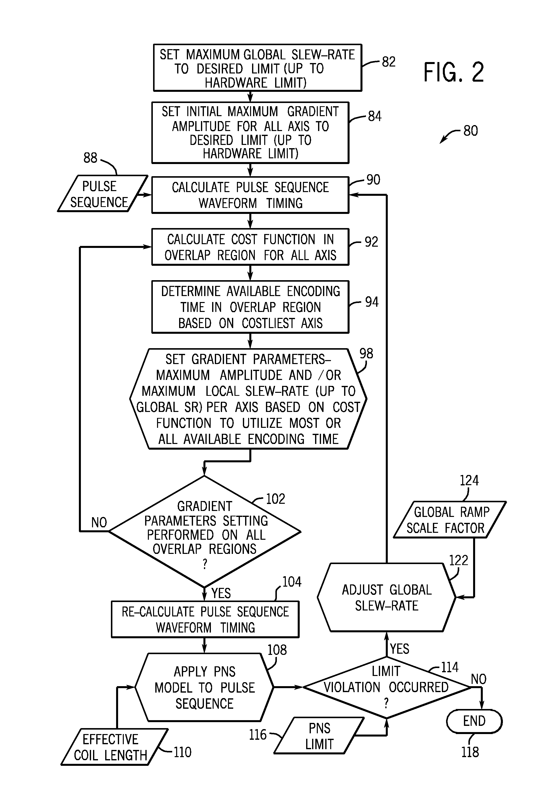
[0005]In one embodiment, a method is provided for modifying a pulse sequence. The method includes the act of calculating timing and amplitudes of a pulse sequence. A cost function analysis is performed on desired gradient overlap regions of the pulse sequence and the available encoding time determined based on the costliest axis per overlap region. A maximum gradient amplitude for one or more gradient axes is reset based on the cost function analysis and / or a local slew rate is reset (up to global slew rate) for one or more gradient axes based on the cost function analysis to utilize some or all of the available encoding time per overlap region. A peripheral nerve stimulation (PNS) model is applied based at least in part on the pulse sequence and an output of the PNS model is compared to a PNS limit. A global slew rate used to calculate the timing of the pulse sequence is adjusted if the output of the PNS model exceeds the PNS limit and timing and amplitudes of the pulse sequence are recalculated based on the adjusted global slew rate and the reset maximum gradient amplitudes and / or the local slew rate. The steps of applying, comparing, adjusting, performing, resetting, and recalculating are repeated until the output of the PNS model is within the PNS limit
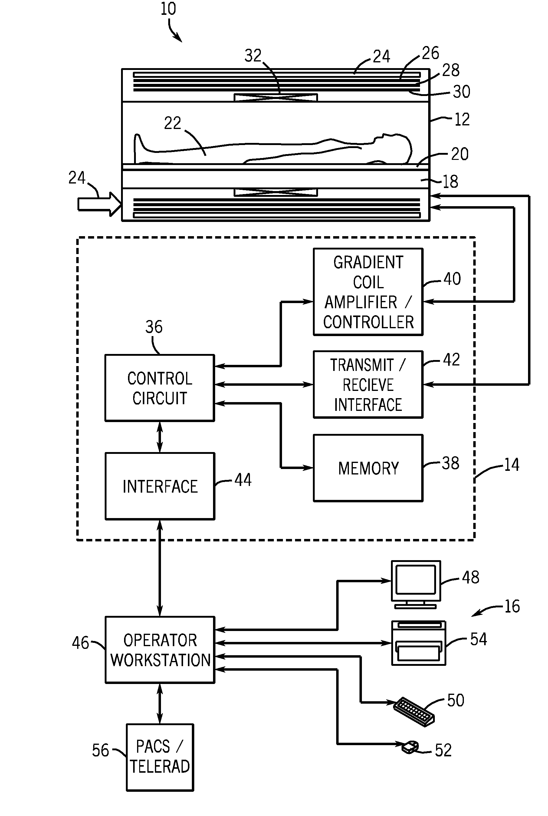
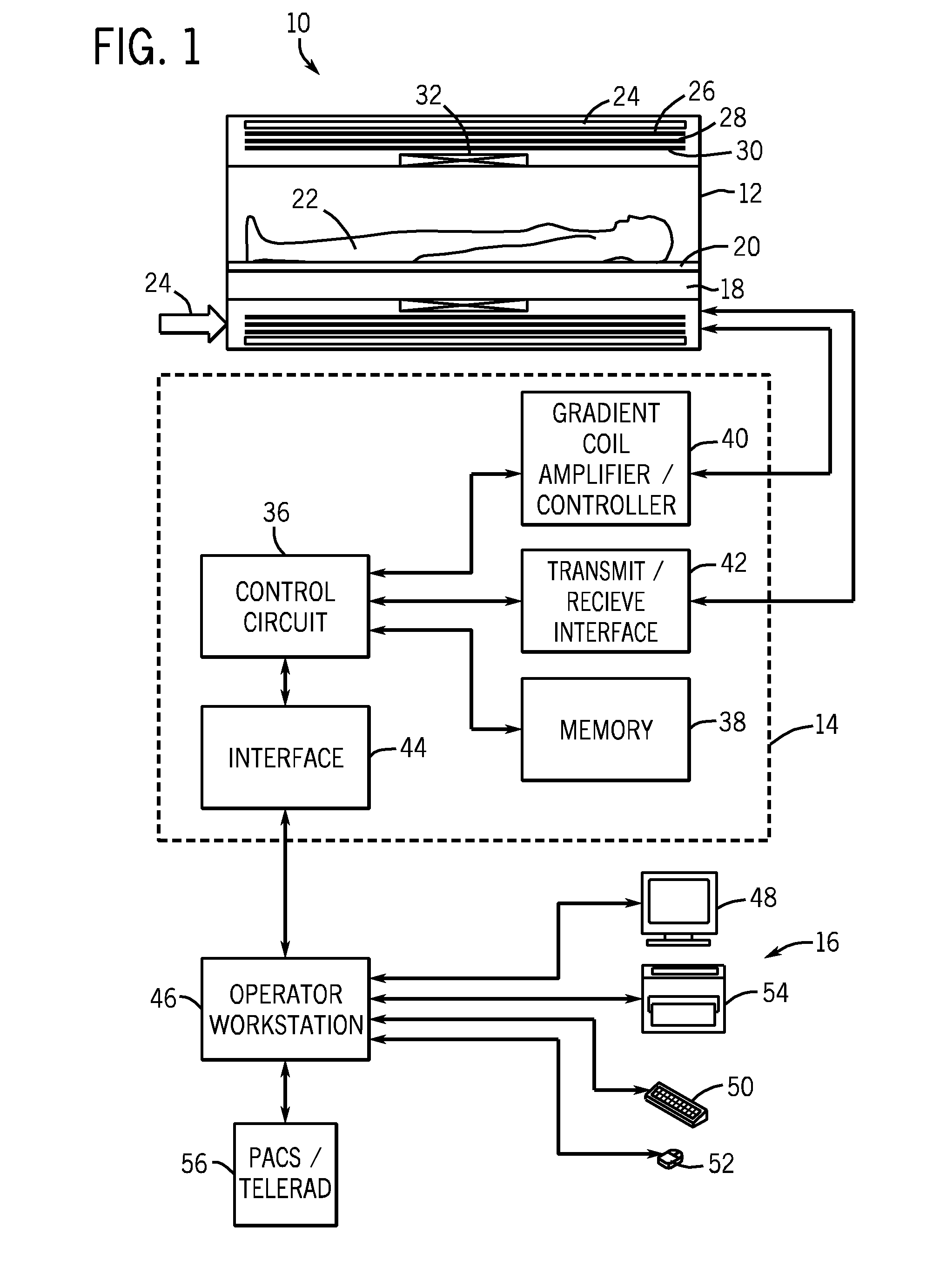
[0006]In another embodiment, a magnetic resonance imaging (MRI) system is provided. The MRI system comprises a MRI scanner and scanner control circuitry capable of controlling operation of the scanner. The scanner control circuitry comprises a memory capable of storing one or more routines for adjusting a pulse sequence and control circuitry capable of implementing the one or more routines. The one or more routines, when executed, calculate timing and amplitudes for a pulse sequence, compare an estimate of peripheral nerve stimulation (PNS) associated with the pulse sequence against a PNS limit, adjust one or more of the slew rate and the maximum gradient amplitude for each axis if the estimate of PNS exceeds the PNS limit, and recalculate the timing and amplitudes for the pulse sequence until the estimate of PNS does not exceed the PNS limit. The MRI system also comprises system control circuitry capable of controlling operation of the scanner control circuitry.

Problems solved by technology

Imaging performance not only depends on the hardware capabilities, but also patient safety constraints imposed on the system.
In some instances it may be difficult to achieve the highest imaging performance due to patient safety constraints imposed on the pulse sequences, which describe the timing and operation of the magnetic and RF fields generated by the imaging system.
Such constraints, however, may limit imaging performance.
Earlier MRI systems were largely limited by the hardware capabilities.
With the recent technological advances, safety constraints are becoming the new bottleneck in achieving the highest possible imaging performance.

Method used


Image

  • Method and system for modifying pulse sequences
  • Method and system for modifying pulse sequences
  • Method and system for modifying pulse sequences

Examples


Embodiment Construction

[0017]Magnetic resonance imaging (MRI) is a useful technology for generating internal views of a patient that might not be easily obtained using other techniques. In addition, to generate images, an MRI system utilizes magnetic fields and radio frequency (RF) energy and, therefore does not subject the patient to X-rays or gamma rays where the patient dosage may be an issue. The timing and strength of the various magnetic and RF fields that may be generated as part of a MRI examination may be described by a pulse sequence diagram. Such a pulse sequence diagram may describe aspects of the examination such as the repetition time (TR) (the time between the application of one RF pulse and the next RF pulse), echo time (TE) (the time between the application of an RF pulse and the signal peak detected at the RF coil), echo spacing, and so forth. In general, improved imaging performance may generally be equated with minimizing or reducing TR, TE, and echo spacing. In theory, these values ma...


PUM


Abstract

Methods and systems are provided for modifying a pulse sequence. In one embodiment, a determination is made whether an estimated peripheral nerve stimulation (PNS) associated with a pulse sequence exceeds a PNS limit. If the estimated PNS exceeds the PNS limit, a slew rate associated with one or more axes of the pulse sequence may be reduced and the maximum gradient amplitudes for each axis of the pulse sequence may be adjusted. In one embodiment, adjustment of the maximum gradient amplitudes or local slew rate may be based upon a cost analysis performed on the pulse sequence.

Description

BACKGROUND[0001]The subject matter disclosed herein relates generally to magnetic resonance imaging systems and, more particularly, to techniques for designing and implementing pulse sequences on magnetic resonance imaging systems.[0002]The use of medical imaging technologies has become commonplace in the medical community. Such imaging technologies typically allow the acquisition of images which depict the internal structures (internal tissues and organs, bones, and so forth) and / or biochemical functions of a patient without the use of invasive procedures. That is, medical imaging technologies typically allow the internal structures and / or functions of a patient to be observed without surgery or other invasive procedures.[0003]One such medical imaging technology is known as magnetic resonance imaging (MRI). MRI systems typically employ magnetic fields and pulses of radio frequency (RF) energy to generate images based on the gyromagnetic properties of tissues and structures within t...

Claims


Application Information

Patent Timeline
Patent Type & Authority Applications(United States)
IPC IPC(8): G01R33/20H03K3/00
CPCG01R33/288H03K6/04G01R33/543G01R33/385
Inventor VU, ANTHONY TIENHUANSUN, WEIBAYRAM, ERSIN
Owner GENERAL ELECTRIC CO
Learn More