State quantity detection method in power converting apparatus and power converting apparatus

a technology of power converting apparatus and detection method, which is applied in the direction of pulse technique, electronic switching, transistor, etc., can solve the problems of detection accuracy and limit in simplification of configuration, and achieve the effect of simple configuration, stable voltage value and high accuracy

Active Publication Date: 2010-12-09
DAIKIN IND LTD
View PDF10 Cites 9 Cited by
  • Summary
  • Abstract
  • Description
  • Claims
  • Application Information

AI Technical Summary

Benefits of technology

[0025]According to the first aspect of the state quantity detection method in the power converting apparatus according to the present invention, and the first aspect of the power converting apparatus according to the present invention, to detect a line voltage between ones of the plurality of input lines, it suffices that only a voltage between the first and second DC power supply lines is detected. This enables amplitude information to be obtained with a high accuracy and enables detection of an instantaneous waveform of an input voltage, as compared with the method of obtaining the amplitude information by detecting a voltage between both ends of a smoothing capacitor to thereby detect a DC voltage as disclosed in Japanese Patent Application Laid-Open No. 5-056682 (1993). Moreover, it is apparent that the detection can be performed with a simpler configuration than in a case where a voltage is directly detected in ones of the plurality of input lines.
[0026]According to the second aspect of the state quantity detection method in the power converting apparatus according to the present invention, and the second aspect of the power converting apparatus according to the present invention, the current-source converter and the voltage-source inverter are operated in synchronization with each other, and therefore a line voltage of the input line and a line current of the output line can be detected at the same timing.
[0027]According to the third aspect of the state quantity detection method in the power converting apparatus according to the present invention, and the third aspect of the power converting apparatus according to the present invention, the current is detected in the longer one of ...

Problems solved by technology

Accordingly, two current detection circuits and one voltage detection circuit are necessary, and there has been a limit in simplification of a configuration.
The vol...

Method used


Image

  • State quantity detection  method in power converting apparatus and power converting apparatus
  • State quantity detection  method in power converting apparatus and power converting apparatus
  • State quantity detection  method in power converting apparatus and power converting apparatus

Examples


first embodiment

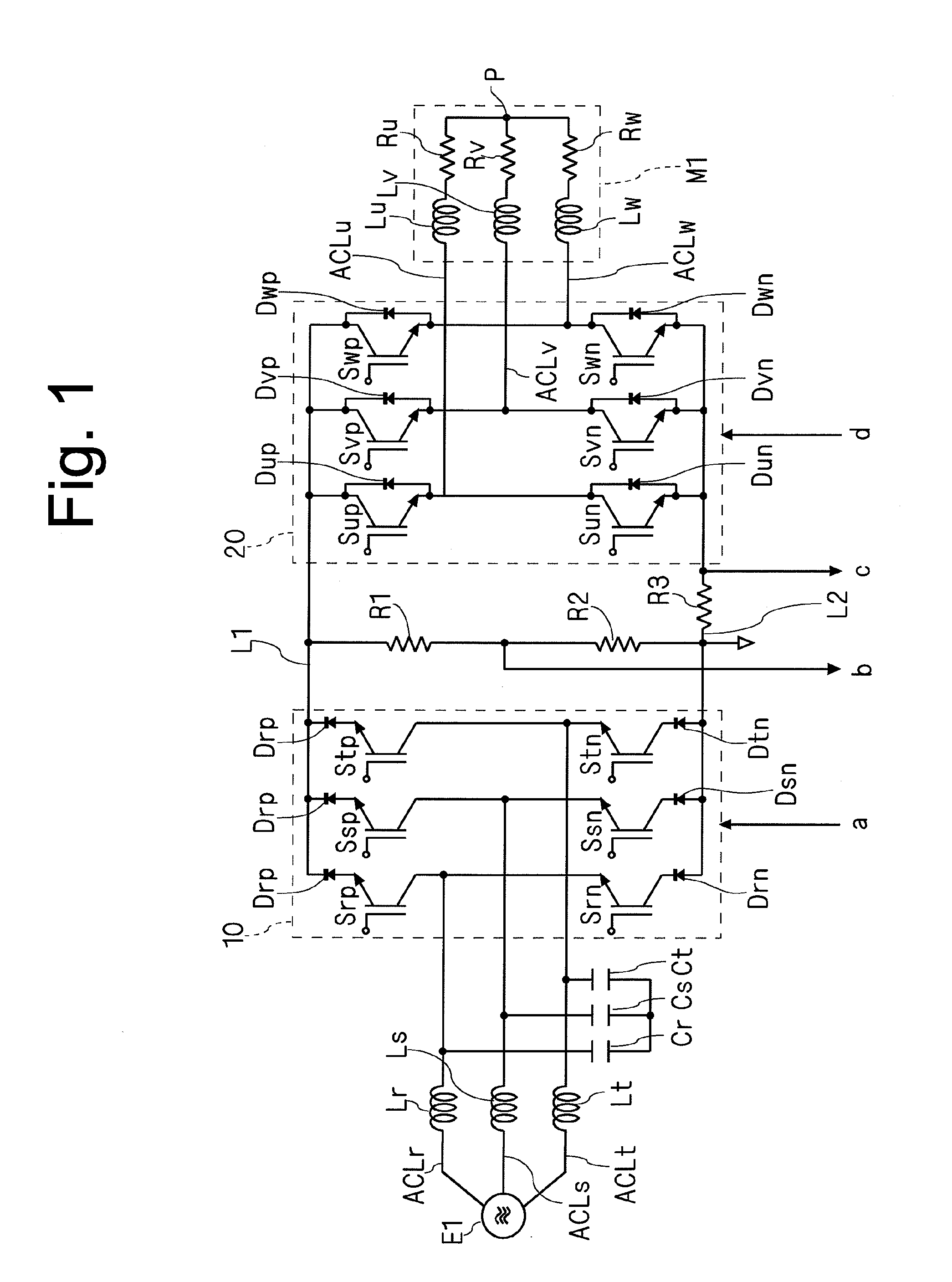
[0058]FIG. 1 shows an exemplary conceptual configuration of a direct power converting apparatus according a first embodiment. The direct power converting apparatus includes a multi-phase power source E1, input lines ACLr, ACLs, ACLt, reactors Lr, Ls, Lt, capacitors Cr, Cs, Ct, a current-source converter 10, DC power supply lines L1, L2, resistors R1, R2, a shunt resistor R3, a voltage-source inverter 20, output lines ACLu, ACLv, ACLw, and a multi-phase motor M1.

[0059]The multi-phase power source E1 is, for example, a three-phase AC power source, and outputs three-phase AC voltages to between one of the input lines ACLr, ACLs, ACLt.

[0060]The reactors Lr, Ls, Lt are provided on the input lines ACLr, ACLs, ACLt, respectively.

[0061]The capacitors Cr, Cs, Ct are provided between ones of the respective input lines ACLr, ACLs, ACLt, by being Y-connected with one another, for example. Specifically, the capacitors Cr, Cs are connected in series between the input lines ACLr, ACLs. The capacit...

second embodiment

[0116]In this embodiment, a description will be given of an exemplary configuration for realizing the control of the power converting apparatus and the state quantity detection method which have been described in the first embodiment.

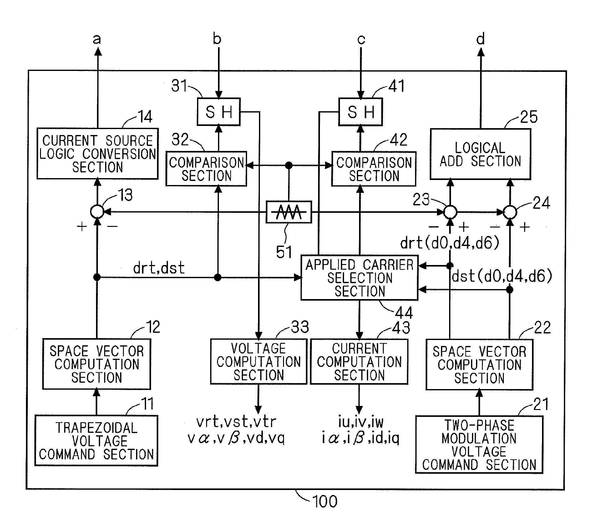
[0117]FIG. 7 shows an exemplary conceptual configuration of a control section which controls the power converting apparatus shown in FIG. 1. The control section 100 has a trapezoidal voltage command section 11, space vector computation sections 12, 22, comparators 13, 23, 24, a current-source logic conversion section 14, a two-phase modulation voltage command section 21, a logical add section 25, sample hold circuits 31, 41, comparison sections 32, 42, a voltage computation section 33, a current computation section 43, an applied carrier selection section 44, and a carrier generation section 51.

[0118]Firstly, a method for generating a switch signal to be applied to the current-source converter 10, and its configuration will be described. In general outl...

third embodiment

[0172]In this embodiment, a description will be given of another exemplary configuration for realizing the control of the power converting apparatus and the state quantity detection method which have been described in the first embodiment.

[0173]FIG. 24 shows an exemplary conceptual configuration of a control section which controls the power converting apparatus shown in FIG. 1. As compared with the second embodiment, an applied signal selection section 45 is provided instead of the applied carrier selection section 44, and the comparison section 42 serves to perform the function of the comparison section 32.

[0174]The comparison section 42 outputs a sampling timing to the sample hold circuits 31, 41, based on comparison between a value obtained from the space vector computation section 22 and a carrier obtained from the carrier generation section 51. For example, with reference to FIG. 23, the comparison section 42 outputs the time points (the times t2′, t4′, t3′, and t1′) at which t...


PUM


Abstract

A current-source converter includes high-arm side switching elements and low-arm side switching elements. A voltage between the DC power supply lines is detected as a line voltage of an input line, based on a conduction pattern of the high-arm side switching elements and the low-arm side switching elements.

Description

TECHNICAL FIELD[0001]The present invention relates to a state quantity detection method in a power converting apparatus, and the power converting apparatus, and for example, relates to a direct power converting apparatus having no power storage means between a converter and an inverter.BACKGROUND ART[0002]Japanese Patent Application Laid-Open No. 3-230767 (1991) discloses a technique of detecting a current in an inverter which converts a DC voltage applied between two DC power supply lines into a three-phase AC voltage. A smoothing capacitor is connected between the DC power supply lines. A shunt resistor is connected to the DC power supply line, at an inverter side relative to the smoothing capacitor. A current flowing in the shunt resistor is detected based on a voltage vector of a voltage outputted by the inverter, and a phase current is obtained by computation using the detected current value.[0003]To operate a power converting apparatus so as to bring an input power factor clos...

Claims


Application Information

Patent Timeline
IPC IPC(8): H03K17/60
CPCH02M5/4585H02M1/0009H02M5/4505H02M5/451H02M5/452H02M7/1557
Inventor SAKAKIBARA, KENICHI
Owner DAIKIN IND LTD
Why Eureka
Try Eureka