

Method of Positioning an Organic, Biological and/or Medical Specimen
- Summary
- Abstract
- Description
- Claims
- Application Information
AI Technical Summary
Benefits of technology
Problems solved by technology
Method used
Image

Examples
Embodiment Construction
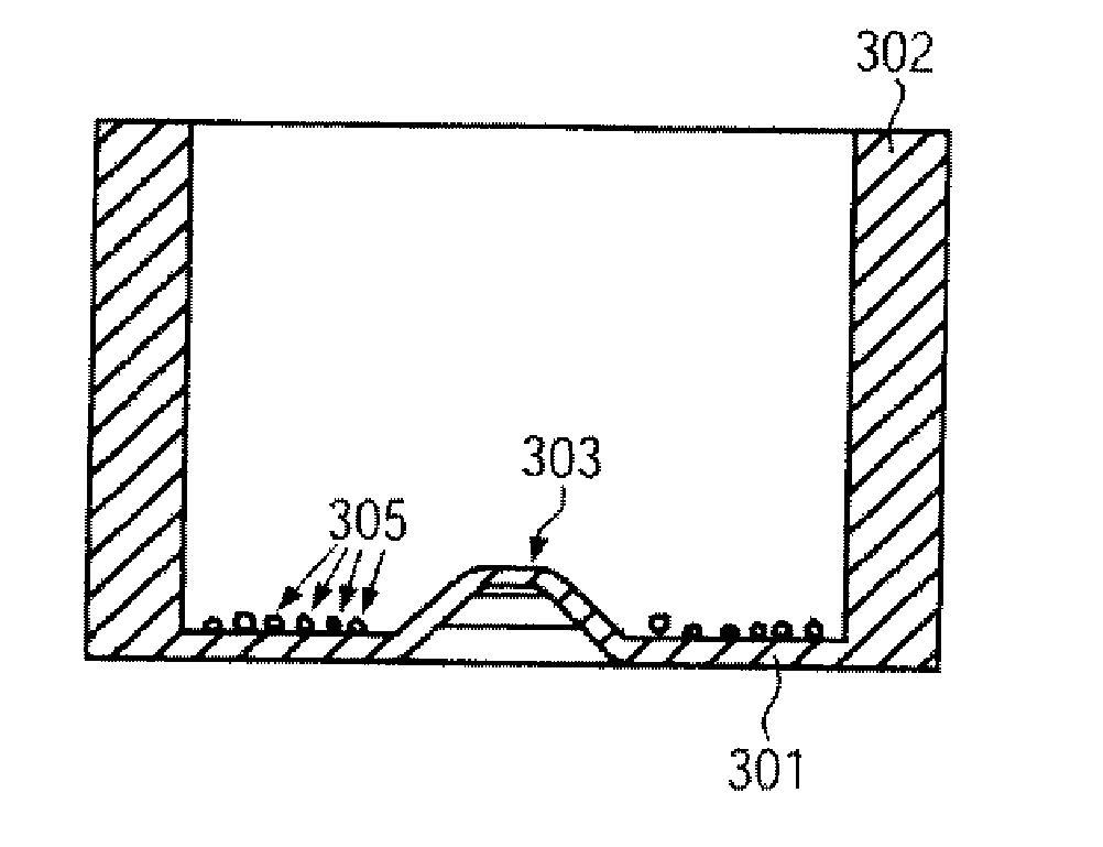
[0104]The organic, biological and / or medical specimen can be a biological cell. In particular a plurality of cells can be positioned. In this way a desired cell distribution in a desired surface region of the specimen carrier can be provided.
[0105]Generally, when filling a specimen carrier or culture container a random distribution of the cells occurs. In the case of simple dishes or jars the cell distribution often depends on the type of filling, i.e. for example, how quickly the cell suspension is pipetted in and how the containers are moved directly after filling. In microfluidic cell culture containers the cell distribution often depends on the geometry of the structures which take up the cell suspension.
[0106]In particular with experiments with biological cells often exact positioning of the cells is required. In this way the local cell density can be defined in order to be able to easily compare results from different experiments against one another, to be able to carry out th...
PUM
 Abstract
Description
Claims
Application Information