Wireless connectivity for sensors

Active Publication Date: 2010-12-09
SENCORMATIC ELETRONICS LLC
View PDF6 Cites 7 Cited by
  • Summary
  • Abstract
  • Description
  • Claims
  • Application Information

AI Technical Summary

Benefits of technology

[0008]The present invention advantageously provides a method and system for establishing wireless communication among EAS sensors and other EAS equipment. The present invention provides a layered addressing approach in facilitating connectivity of devices to the network which allows existing wired networks to seamlessly connect to a wireless node in the wireless network.

Problems solved by technology

Sensors and other EAS equipment have an installation deployment cost associated with the installation of wires for the transfer of information.
Wireless communication has been costly and the communication protocol stacks consume product memory.
Additionally, a method for seamlessly connecting a wired network device to a wireless network has not been easily and cost effectively devised.
However wired connections increase deployment burden.
Higher cost wireless solutions implementing complex communication protocol stacks have been used in some deployments but are not effective in low cost sensors and deployments due to the expensive processing and memory costs associated with implementing complex communication protocol stacks.
Some wireless solutions require configuration and setups that are time consuming and inflexible, increasing the deployment and maintenance cost.
However, the protocol stack as defined for Zigbee consumes a large amount of memory and requires a rather complex configuration.
Other networks residing in the 2.45 GHz and higher frequency ranges occupy the same bandwidth space as customer solutions using IEEE 802.11, i.e., “Wi-Fi.” These frequencies introduce challenges with Information Technology (“IT”) wireless network interference and increase the maintenance burden on IT departments.

Method used


Image

  • Wireless connectivity for sensors
  • Wireless connectivity for sensors
  • Wireless connectivity for sensors

Examples


Embodiment Construction

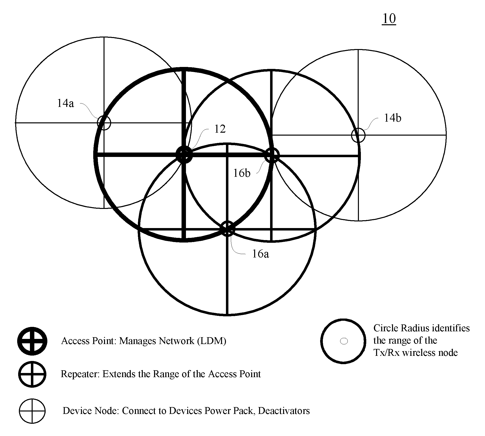
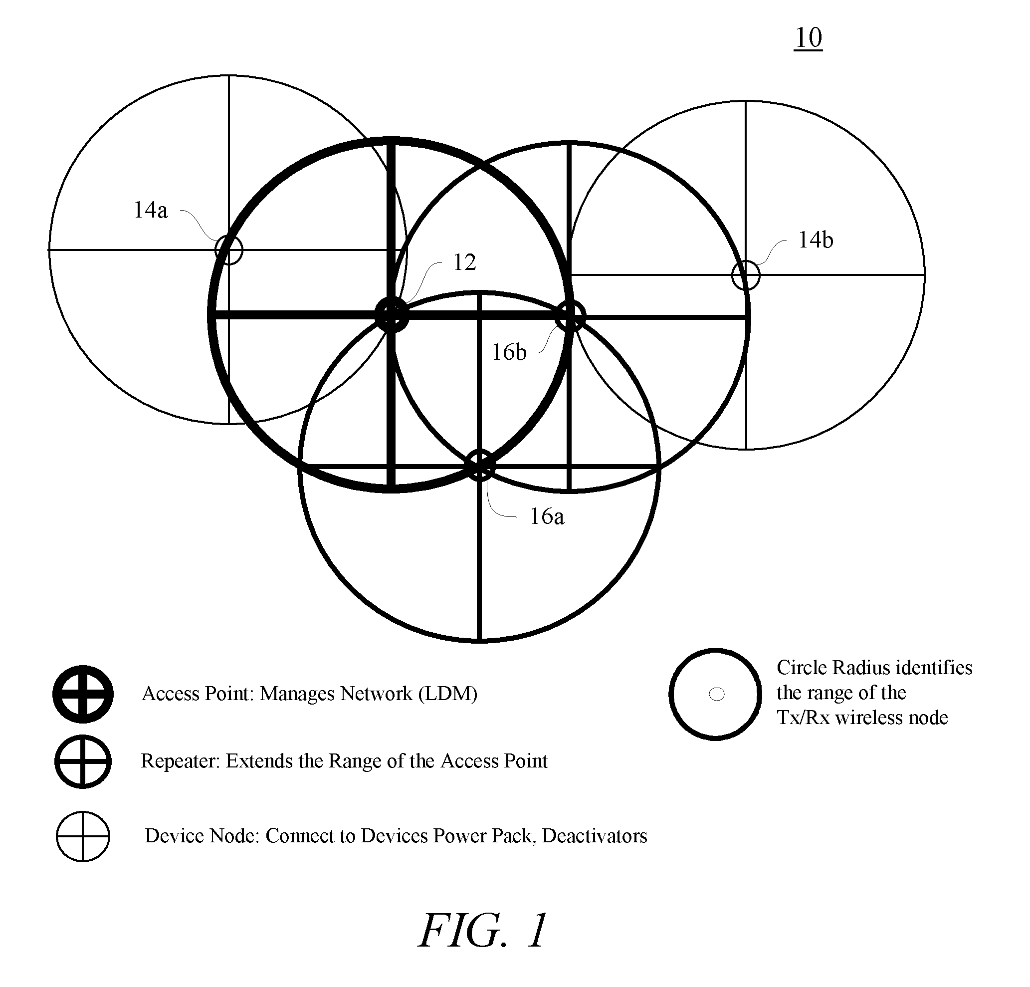
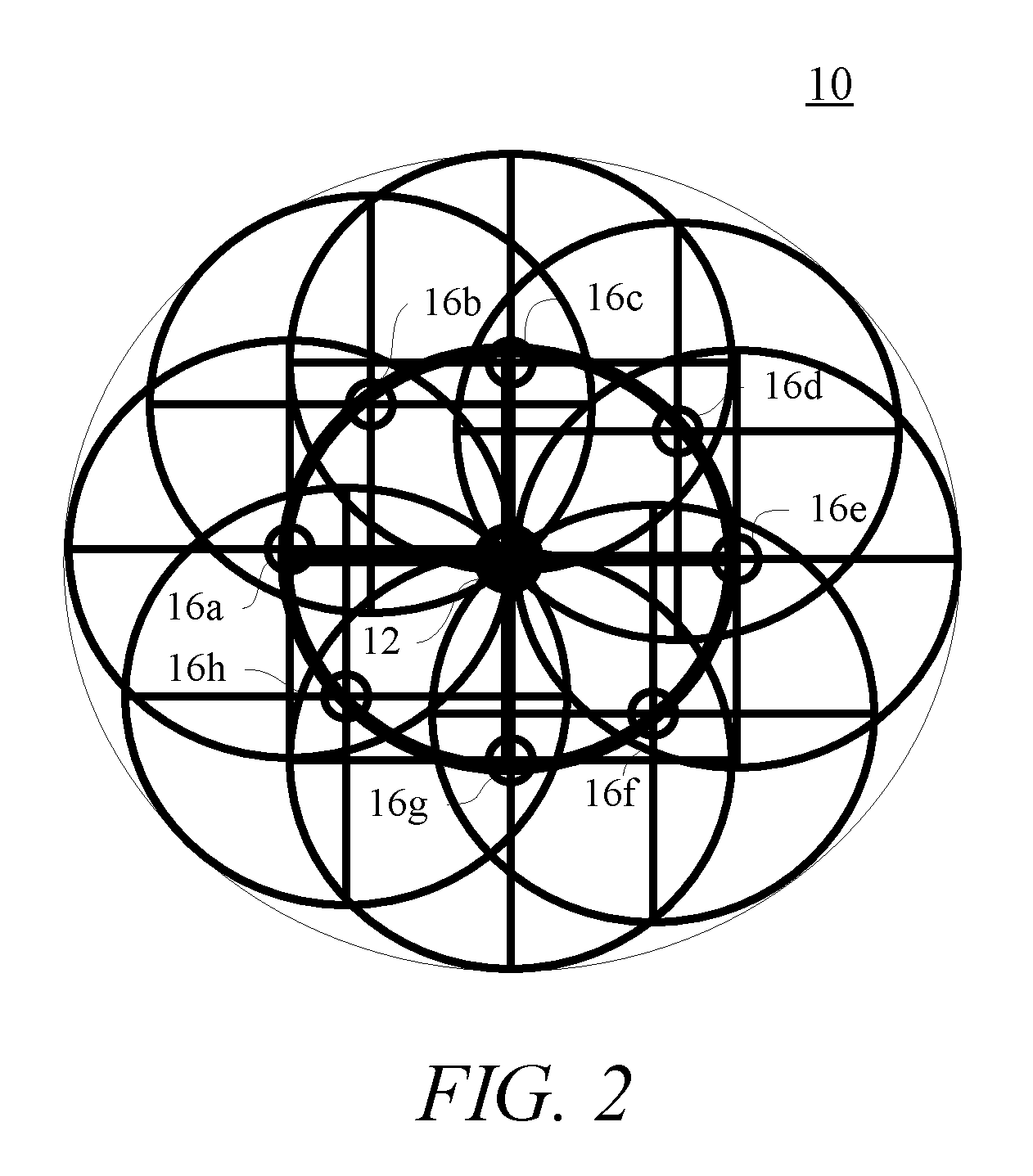
[0024]Before describing in detail exemplary embodiments that are in accordance with the present invention, it is noted that the embodiments reside primarily in combinations of apparatus components and processing steps related to implementing a system and method for wirelessly connecting electronic article surveillance (“EAS”) equipment and EAS sensors. Accordingly, the system and method components have been represented where appropriate by conventional symbols in the drawings, showing only those specific details that are pertinent to understanding the embodiments of the present invention so as not to obscure the disclosure with details that will be readily apparent to those of ordinary skill in the art having the benefit of the description herein.

[0025]As used herein, relational terms, such as “first” and “second,”“top” and “bottom,” and the like, may be used solely to distinguish one entity or element from another entity or element without necessarily requiring or implying any phys...


PUM


Abstract

A wireless access point communicates messages in an electronic article surveillance (EAS) network. The EAS network includes at least one EAS sensor hard-wired to at least one wireless device node. The wireless access point includes a wired communication interface, a wireless communication interface and a controller. The controller is electrically coupled to the wired communication interface and to the wireless communication interface. The wired communication interface operates to receive a message. The message includes a sub-layer address corresponding to an EAS sensor. The wireless communication interface operates to broadcast the message and to receive an acknowledgement of the broadcast message. The acknowledgment originates from the EAS sensor corresponding to the sub-layer address. The controller operates to transfer the message between the wired communication interface and the wireless communication interface.

Description

CROSS-REFERENCE TO RELATED APPLICATION[0001]n / aSTATEMENT REGARDING FEDERALLY SPONSORED RESEARCH OR DEVELOPMENT[0002]n / aFIELD OF THE INVENTION[0003]The present invention relates generally to an electronic article surveillance (“EAS”) and more specifically to a method and system for establishing wireless connectivity among EAS devices including EAS sensors.BACKGROUND OF THE INVENTION[0004]Sensors and other EAS equipment have an installation deployment cost associated with the installation of wires for the transfer of information. Wireless communication has been costly and the communication protocol stacks consume product memory. Additionally, a method for seamlessly connecting a wired network device to a wireless network has not been easily and cost effectively devised.[0005]The use of wired connections for low cost sensors has been extensively used. However wired connections increase deployment burden. Higher cost wireless solutions implementing complex communication protocol stacks ...

Claims


Application Information

Patent Timeline
IPC IPC(8): G05B23/02H04W84/02
CPCG08B13/2402G08B13/24G08B21/24G08C17/02G08C19/00
Inventor ALICOT, JORGE F.RELIHAN, TIMOTHY J.
Owner SENCORMATIC ELETRONICS LLC
Why Eureka
Try Eureka