Method and system for dynamic control of output power of a leaky wave antenna

a leaky wave antenna and output power technology, applied in the field of wireless communication, can solve the problems of power inefficiency of transmitters and/or receivers in comparison to other blocks of portable communication devices

Active Publication Date: 2010-12-09
AVAGO TECH INT SALES PTE LTD
View PDF111 Cites 50 Cited by
  • Summary
  • Abstract
  • Description
  • Claims
  • Application Information

AI Technical Summary

Benefits of technology

[0010]A system and / or method for dynamic control of output power of a leaky wave antenna as shown in and / or described in connection with at least one of the figures, as set forth more completely in the claims.

Problems solved by technology

Additionally, transmit and / or receive circuitry within such mobile wireless devices often account for a significant portion of the power consumed within these devices.
Moreover, in some conventional communication systems, transmitters and / or receivers are often power inefficient in comparison to other blocks of the portable communication devices.

Method used


Image

  • Method and system for dynamic control of output power of a leaky wave antenna
  • Method and system for dynamic control of output power of a leaky wave antenna
  • Method and system for dynamic control of output power of a leaky wave antenna

Examples


Embodiment Construction

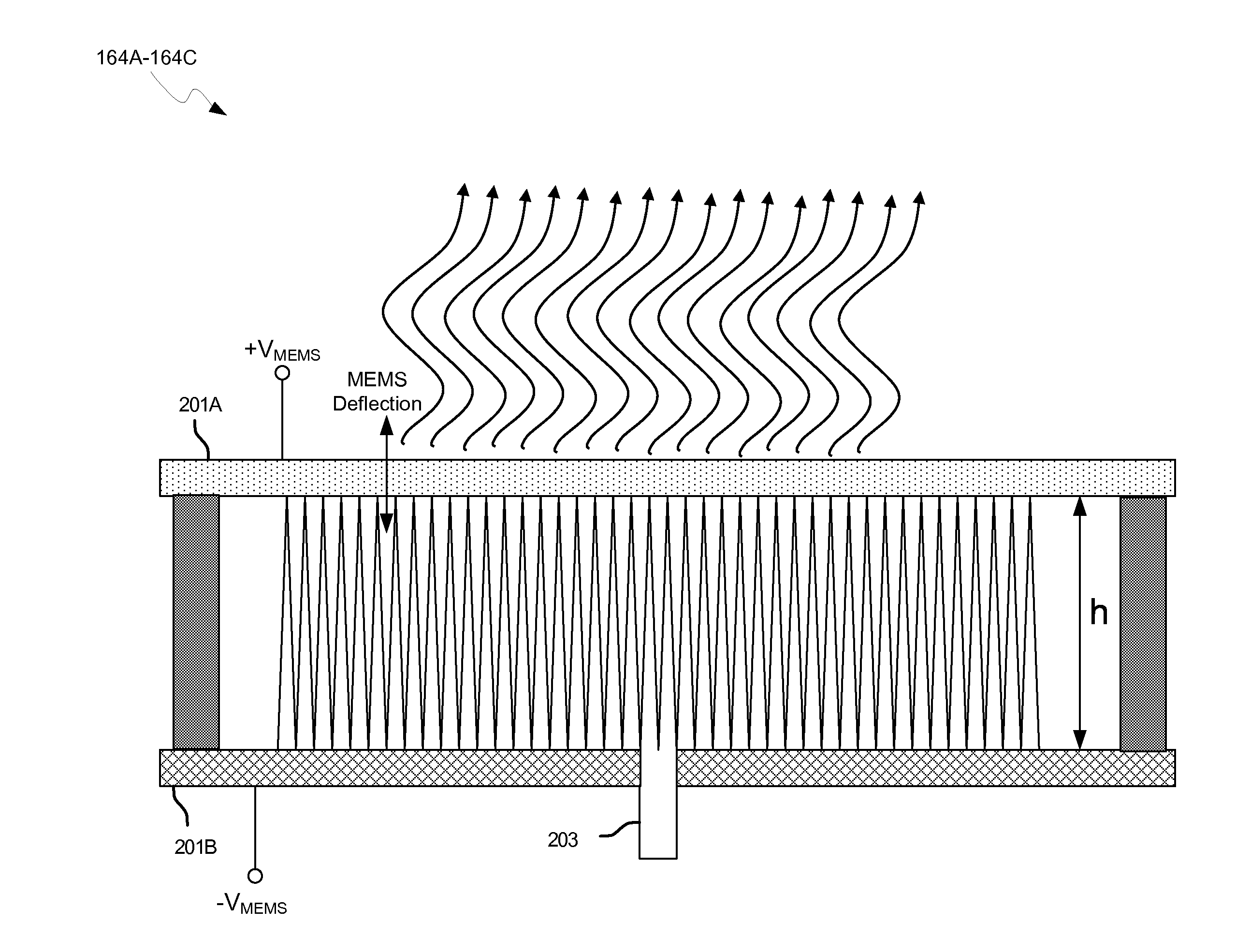
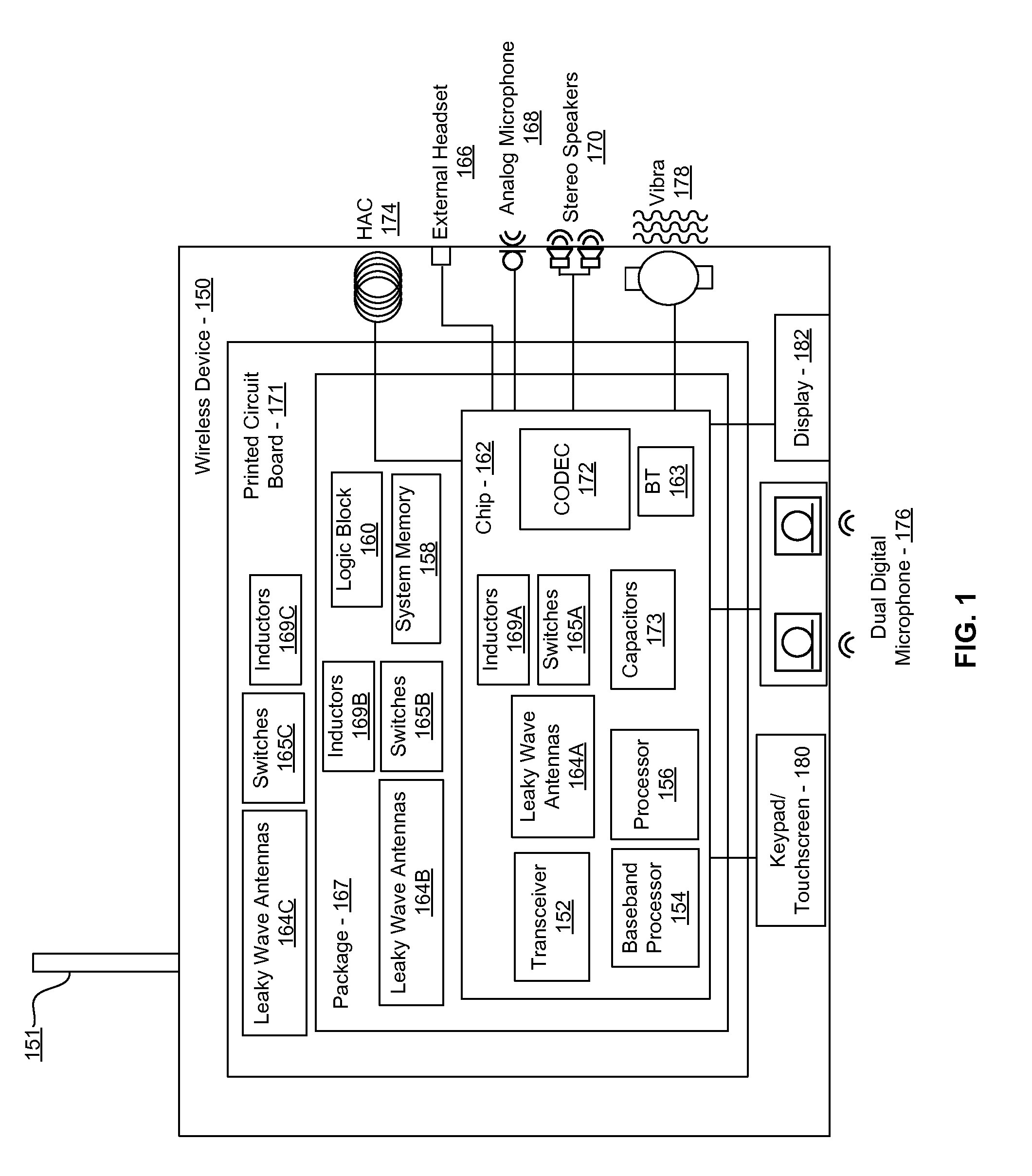
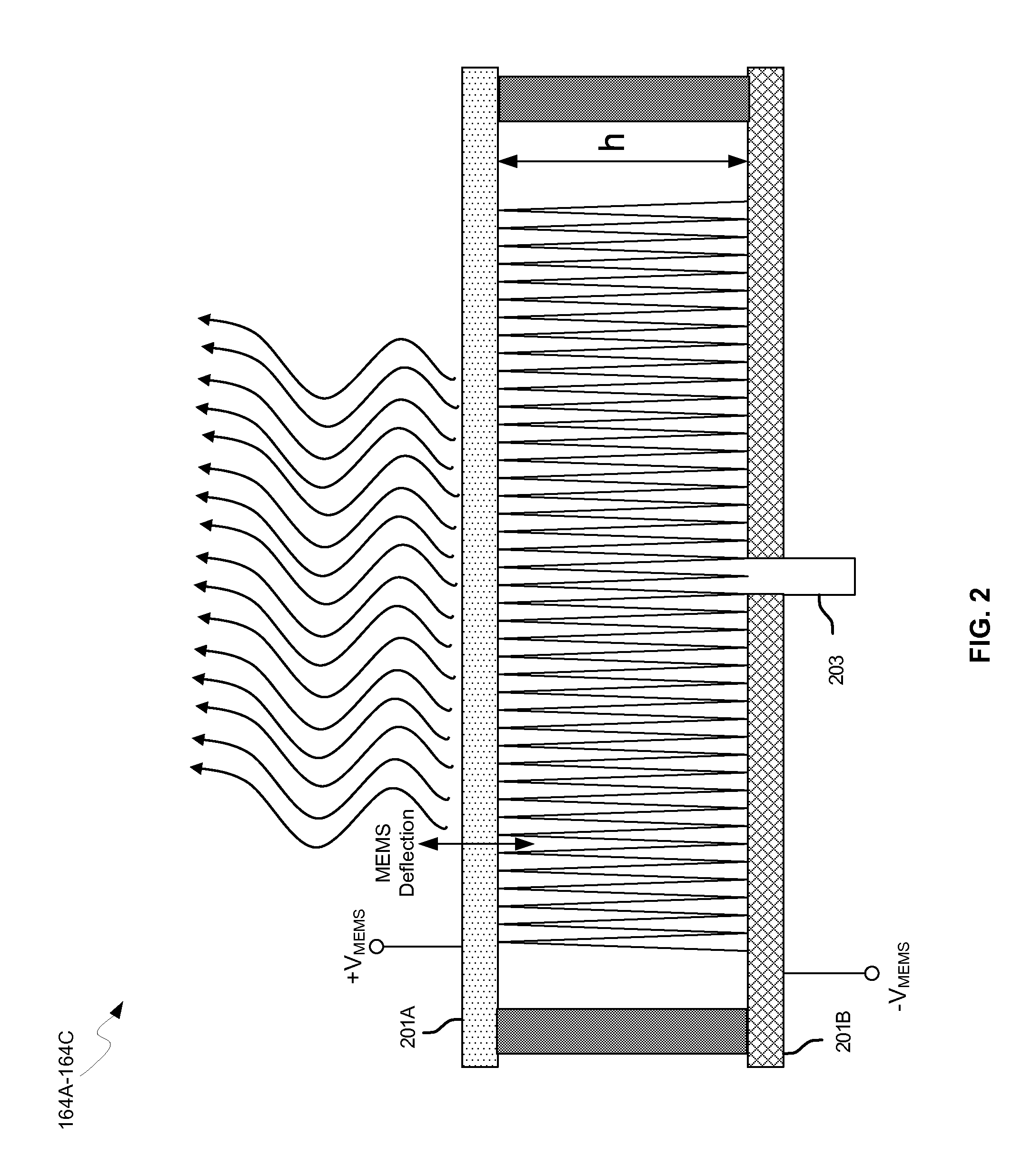
[0022]Certain aspects of the invention may be found in a method and system for dynamic control of output power of a leaky wave antenna. Exemplary aspects of the invention may comprise configuring one or more leaky wave antennas in a wireless device to transmit RF signals at a desired frequency. The leaky wave antennas may be integrated in one or more support structures. The support structures may comprise one or more of: an integrated circuit, an integrated circuit package, and a printed circuit board. One or more impedances that are coupled to the one or more enabled leaky wave antennas and to a power amplifier enabled to amplify the RF signals may be dynamically configured. A resonant frequency of the one or more enabled leaky wave antennas may be tuned. The one or more enabled leaky wave antennas may be configured to transmit the RF signals at a desired angle from a surface of the support structure. The RF signals may be communicated between regions within the support structures....


PUM


Abstract

Methods and systems for dynamic control of output power of a leaky wave antenna (LWA) are disclosed and may include configuring one or more LWAs in a wireless device to transmit RF signals at a desired frequency. The LWAs may be integrated in support structures, including an integrated circuit, an integrated circuit package, and/or a printed circuit board. Impedances that are coupled to the LWAs and to a power amplifier enabled to amplify the RF signals may be dynamically configured. A resonant frequency of the LWAs may be tuned, which may be configured to transmit the RF signals at a desired angle from a surface of the support structure. The LWAs may include microstrip or coplanar waveguides where a cavity height of the LWAs may be configured by controlling spacing between conductive lines in the waveguides. The impedances may include capacitor arrays and/or inductors in the support structures.

Description

CROSS-REFERENCE TO RELATED APPLICATIONS / INCORPORATION BY REFERENCE[0001]This application makes reference to, claims the benefit from, and claims priority to U.S. Provisional Application Ser. No. 61 / 246,618 filed on Sep. 29, 2009, and U.S. Provisional Application Ser. No. 61 / 185,245 filed on Jun. 9, 2009.[0002]This application also makes reference to:U.S. patent application Ser. No. 12 / 650,212 filed on Dec. 30, 2009;U.S. patent application Ser. No. 12 / 650,295 filed on Dec. 30, 2009;U.S. patent application Ser. No. 12 / 650,277 filed on Dec. 30, 2009;U.S. patent application Ser. No. 12 / 650,192 filed on Dec. 30, 2009;U.S. patent application Ser. No. 12 / 650,224 filed on Dec. 30, 2009;U.S. patent application Ser. No. 12 / 650,176 filed on Dec. 30, 2009;U.S. patent application Ser. No. 12 / 650,246 filed on Dec. 30, 2009;U.S. patent application Ser. No. 12 / 650,292 filed on Dec. 30, 2009;U.S. patent application Ser. No. 12 / 650,324 filed on Dec. 30, 2009;U.S. patent application Ser. No. 12 / 708,36...

Claims


Application Information

Patent Timeline
Patent Type & Authority Applications(United States)
IPC IPC(8): H01Q13/20H01Q9/00
CPCH01Q1/2283H01Q13/22H04B5/0031H01Q15/006G01S13/06H01Q13/20H04B1/04H04B7/24H04B1/0458H01L2224/16225H01L2224/32225H01L2224/73204H01L2924/13091H01L2924/00G06K7/10316H01Q15/0066H01Q15/23H01Q19/06
Inventor ROFOUGARAN, AHMADREZAROFOUGARAN, MARYAM
Owner AVAGO TECH INT SALES PTE LTD
Why Eureka
Try Eureka