Inspection of a substrate using multiple cameras

a technology of optical inspection and camera, applied in the field of automatic optical inspection, can solve the problems of high-precision mounting and motion assembly, cost-intensive, and constraint, and achieve the effect of reducing the cost of such systems and ensuring the precision of the motion assembly

Active Publication Date: 2010-12-09
ORBOTECH LTD
View PDF13 Cites 79 Cited by
  • Summary
  • Abstract
  • Description
  • Claims
  • Application Information

AI Technical Summary

Benefits of technology

[0007]In embodiments of the present invention, on the other hand, an image processor registers neighboring images by aligning image features in areas of overlap between the images. (The term “features,” as used in the context of the present patent application and in the claims, refers to any and all recognizable characteristics of the pixel values taken over a given area of the image, including not only corners and edges, for example, but also gray-scale gradations.) The image registration may be carried out continuously over all the images during the scan, so that the image processor can determine global positions of the defects without accumulated error. The image processor is thus able to combine the images and locate defects in the sample with a position accuracy that is finer than the position tolerance of the motion assembly. Consequently, the precision of the motion assembly may be relaxed in systems based on the principles of the present invention, and the cost of such systems may thus be reduced considerably by comparison with systems known in the art.

Problems solved by technology

Meeting this alignment constraint requires costly, high-precision mounting and motion assemblies to scan the FOV of the cameras over the sample with the required position accuracy.

Method used


Image

  • Inspection of a substrate using multiple cameras
  • Inspection of a substrate using multiple cameras
  • Inspection of a substrate using multiple cameras

Examples


Embodiment Construction

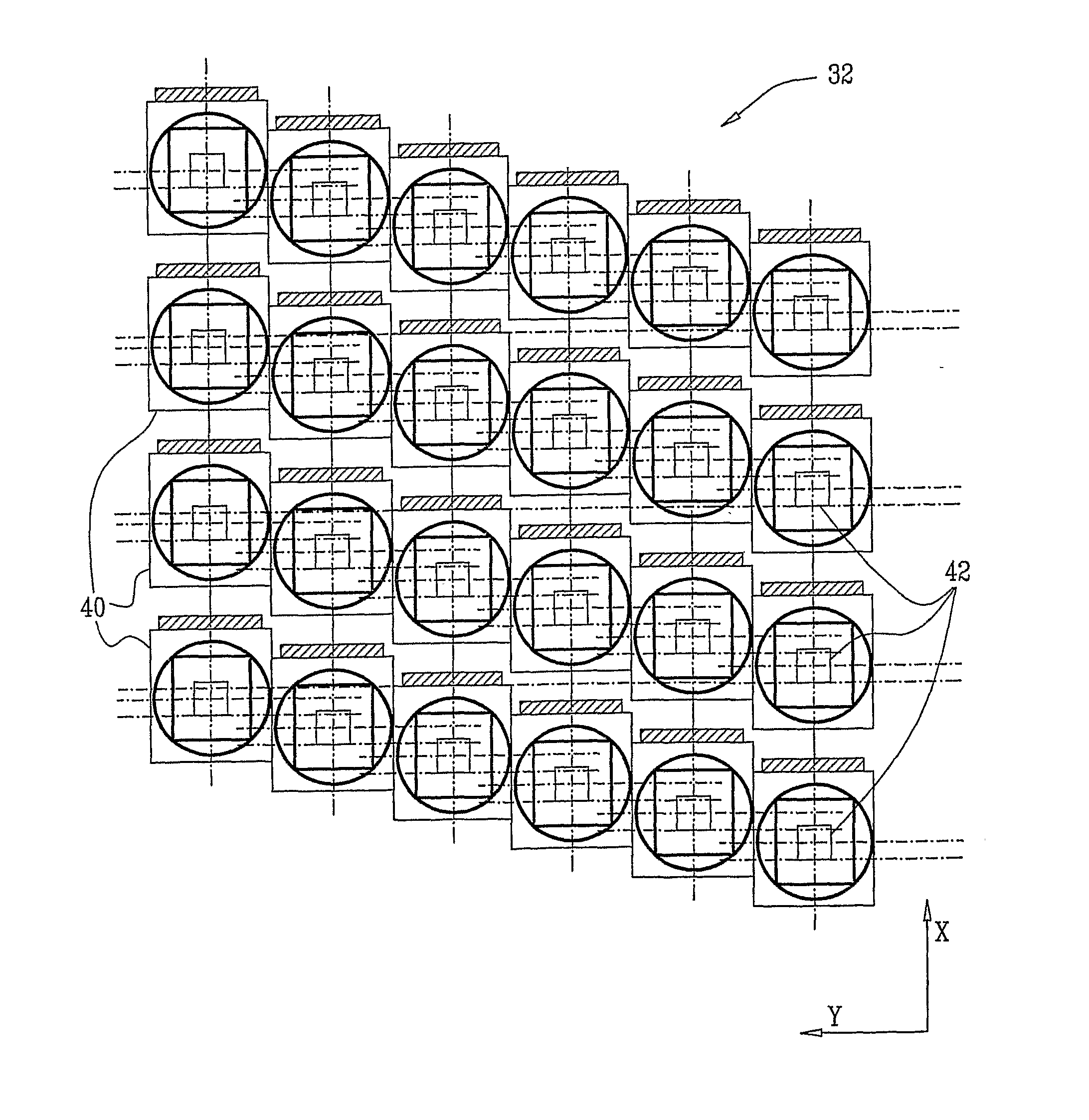
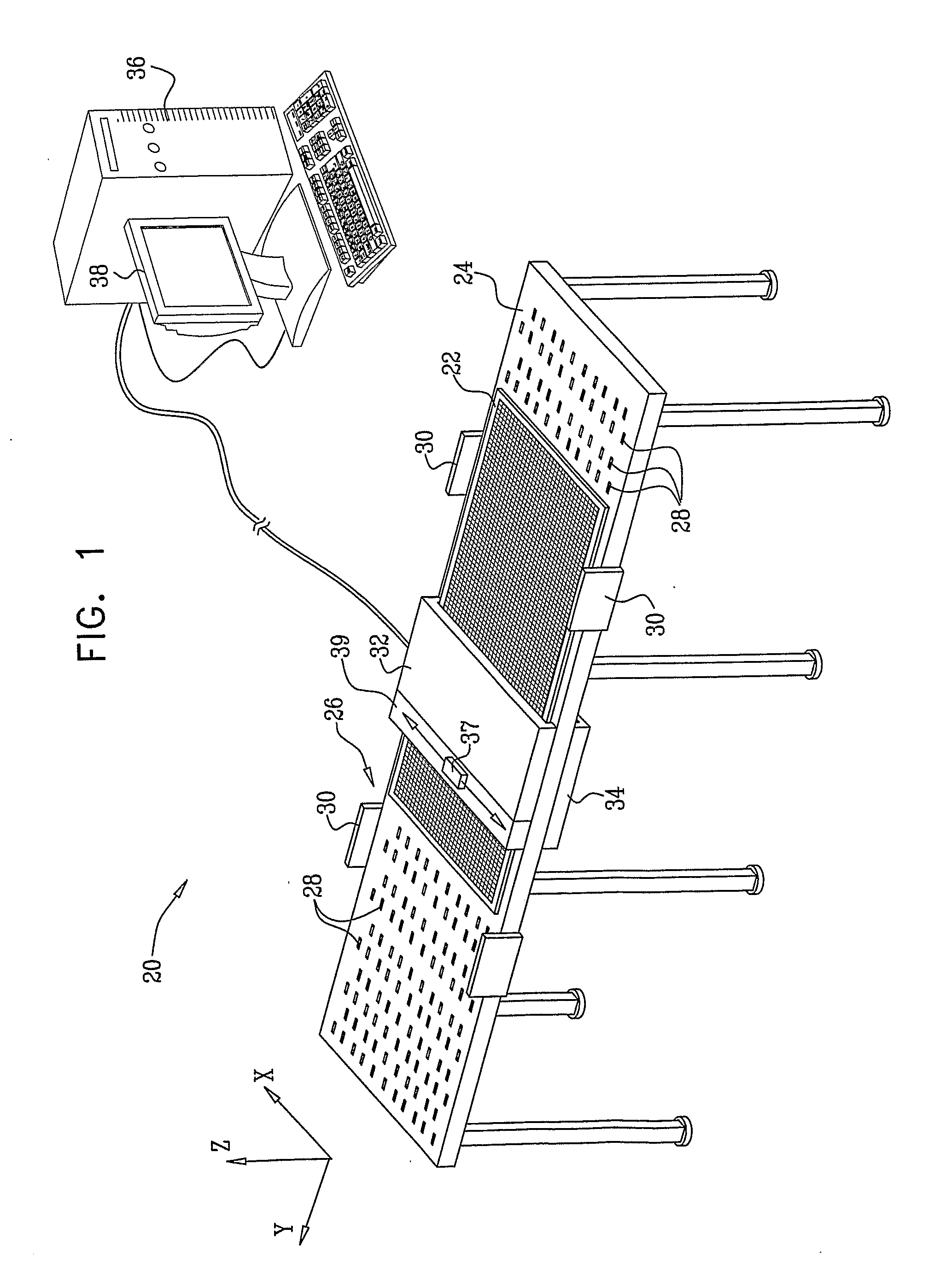
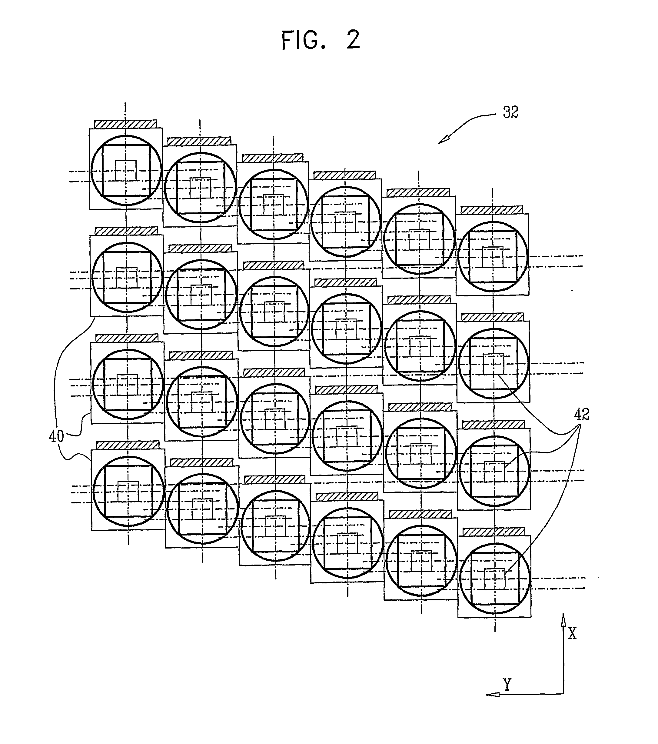
[0029]FIG. 1 is a schematic, pictorial illustration of a system 20 for automated optical inspection of a sample 22, in accordance with an embodiment of the present invention. In the illustrated embodiment, the sample is a flat panel display (FPD), which comprises a large glass substrate with appropriate circuit components formed on its upper surface. (The dimensions of the glass substrates that are currently used in manufacturing FPDs may be as large as 246×216 cm.) Alternatively, system 20 may be adapted, mutatis mutandis, for inspection of generally planar substrates of other types, such as printed circuit boards and integrated circuit wafers. Furthermore, the principles of the present invention may be applied in inspection of non-planar samples, as well

[0030]During inspection, sample 22 is supported by a table 24 with an integrated motion assembly 26. In the example shown in FIG. 1, the motion assembly comprises an array of wheels 28, which propel the sample in the scan direction...


PUM


Abstract

Apparatus for inspection includes an imaging assembly, including a plurality of cameras, which are mounted in different, respective locations in the imaging assembly and are configured to capture respective images of a sample. A motion assembly is configured to move at least one of the imaging assembly and the sample so as to cause the imaging assembly to scan the sample with a scan accuracy that is limited by a predetermined position tolerance. An image processor is coupled to receive and process the images captured by the cameras so as to locate a defect in the sample with a position accuracy that is finer than the position tolerance.

Description

FIELD OF THE INVENTION[0001]The present invention relates generally to automated optical inspection, and specifically to systems and methods that use multiple cameras to inspect an object.BACKGROUND OF THE INVENTION[0002]Systems for automated optical inspection (AOI) commonly use electronic imaging cameras. As defined herein, such a camera contains an image sensor, i.e., an integrated two-dimensional (2D) array of detector elements, such as a charge-coupled device (CCD) or complementary metal-oxide semiconductor (CMOS) array, along with suitable optics. In some applications, the area of a sample that is to be inspected is larger than the field of view (FOV) of the image sensor. In such cases, the camera typically captures multiple images as the FOV is scanned over the sample, and an image processor combines the information in these images in order to detect defects or other features of the sample. (Other AOI systems use line arrays and TDI sensors.)[0003]In some AOI systems of this ...

Claims


Application Information

Patent Timeline
Patent Type & Authority Applications(United States)
IPC IPC(8): H04N7/18G06K9/00
CPCG01N21/956G06T7/0004G06T7/0028G06T2207/30108G06T2207/10016G01N21/95684G01N21/8851G06T7/33
Inventor SAPHIER, OFERSHAPPIRA, ISRAELDAVIDI, YAAKOV
Owner ORBOTECH LTD
Why Eureka
Try Eureka