
Industrial computer

Active Publication Date: 2010-12-09
PEGATRON
View PDF9 Cites 18 Cited by
  • Summary
  • Abstract
  • Description
  • Claims
  • Application Information

AI Technical Summary

Benefits of technology

[0013]According to the industrial computer in the embodiment of the invention, the heat dissipation unit corresponds to the storage unit, and the heat dissipation unit may include a heat sink, a heat dissipation fin, a heat dissipation plate, a heat pipe, a heat dissipation fan, or a combination thereof. Therefore, the heat dissipation of the storage unit can be greatly improved by the heat dissipation element such as a heat dissipation fin or a heat dissipation fan and so on, and a heat dissipation structure such as a heat dissipation hole may be avoided to satisfy industrial standard requirements.

Problems solved by technology

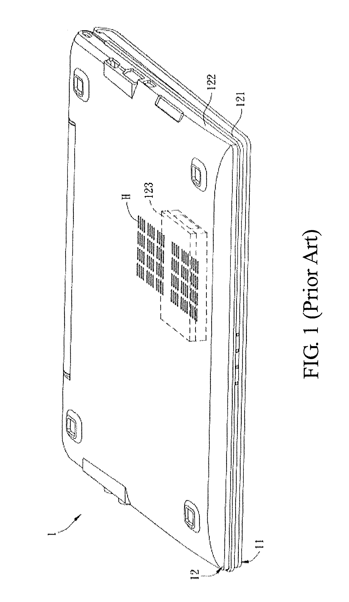
However, when an environmental temperature of the notebook computer 1 is harsh, the heat generated from the hard disk drive 123 fails to be effectively dissipated from the heat dissipation hole H. Further, since the heat dissipation hole H fails to achieve a waterproof and dustproof effect, the notebook computer 1 fails to satisfy standard requirements of the industrial computer.
However, the closed casing may cause a worse heat dissipation and the internal temperature of the casing may increase to cause instability of the whole system.

Method used


Image

  • Industrial computer
  • Industrial computer
  • Industrial computer

Examples


first embodiment

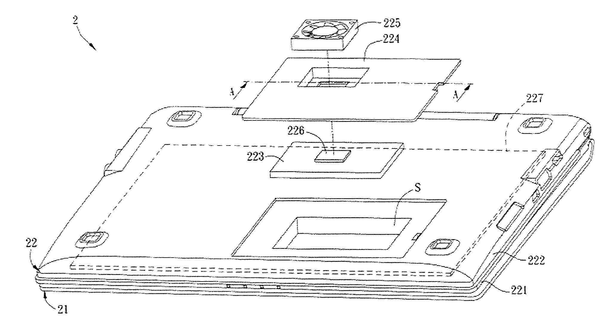
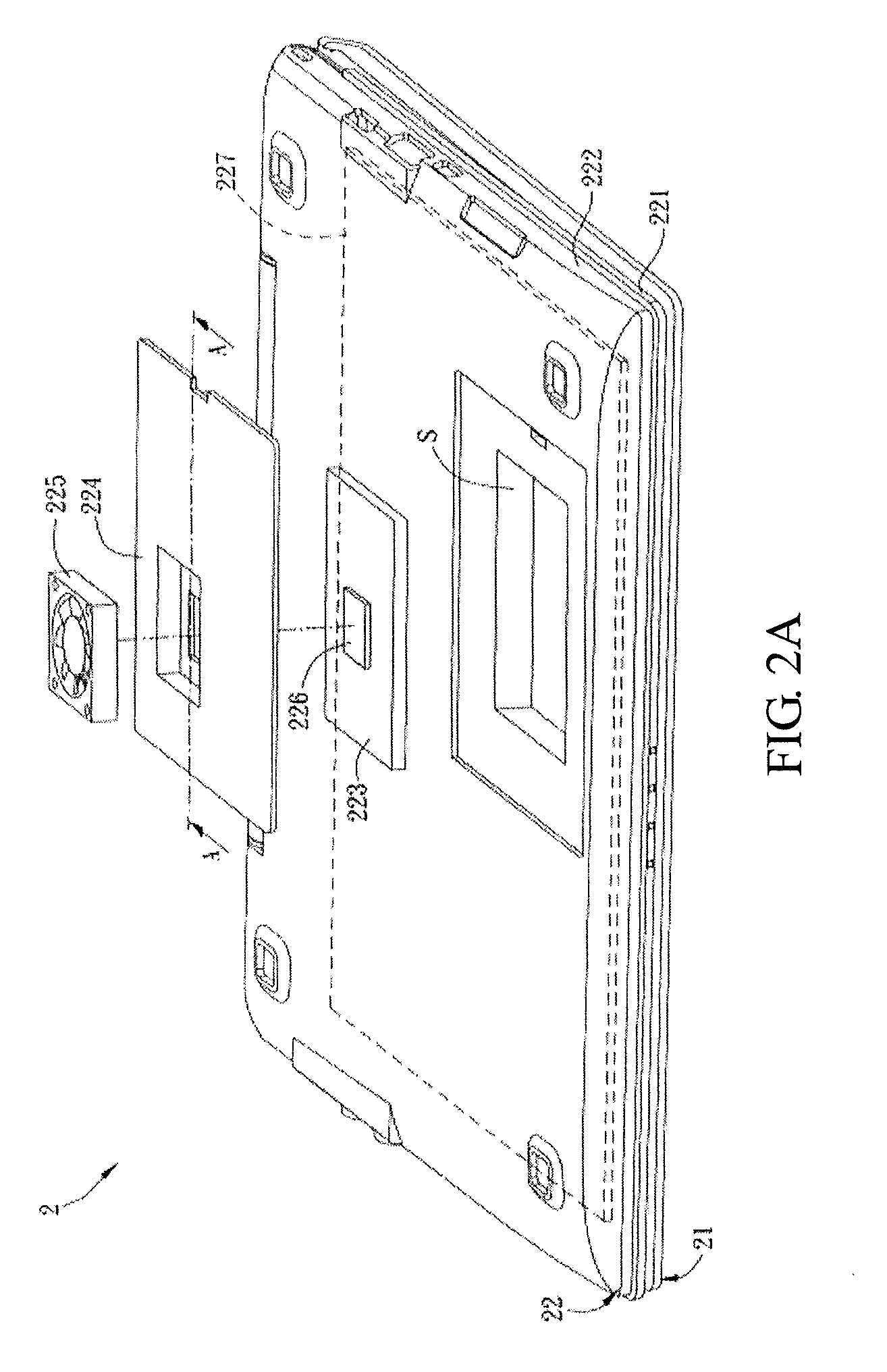
[0021]FIG. 2A is a schematic diagram showing an industrial computer 2 according to a first embodiment of the invention. FIG. 2B is a sectional schematic diagram showing the industrial computer 2 along a line A-A in FIG. 2A. In FIG. 2B, only a second casing 222, a storage unit 223, a cover 224, and a heat dissipation unit 225 are shown for clear description.

[0022]The industrial computer 2 includes a display portion 21, a main body portion 22, a first casing 221, a second casing 222, a storage unit 223, a cover 224, and a heat dissipation unit 225.

[0023]The first casing 221 and the second casing 222 may be made of metal, an alloy, or a high polymer. The second casing 222 and the first casing 221 form a closed casing, and the outside of the second casing 222 has a containing area S.

[0024]The storage unit 223 is disposed at the containing area S. The storage unit 223 may be a solid state drive (SSD) or a conventional hard disk drive (HDD).

[0025]The cover 224 is removably assembled at th...

second embodiment

[0035]FIG. 4 is a schematic diagram showing an industrial computer 3 according to a second embodiment of the invention. The industrial computer 3 includes a display portion 31, a main body portion 32, a first casing 321, a second casing 322, a storage unit 323, a cover O, and a heat dissipation unit 325. In addition, in the embodiment, the industrial computer 3 may include a thermal pad 326 and a main body unit 327.

[0036]The difference between this embodiment and the first embodiment is that the storage unit 323 of the industrial computer 3 is disposed in a closed casing formed by the first casing 321 and the second casing 322, and an opening of a containing area of the second casing 322 is disposed at a lateral surface of the casing. The cover O is openably assembled at the second casing 322, The cover O may include a cover plate O2 and a hinge structure O1. The cover plate O2 rotates by the hinge structure O1 to cover or expose the containing area. The storage unit 323 is disposed...


PUM


Abstract

An industrial computer includes a first casing, a second casing, a storage unit, a cover, and a heat dissipation unit. The second casing and the first casing form a closed casing, and the outside of the second casing has a containing area. The storage unit is disposed at the containing area. The cover is removably assembled at the second casing to cover the containing area and contact the storage unit. The heat dissipation unit is disposed at the cover.

Description

CROSS-REFERENCE TO RELATED APPLICATIONS[0001]This Non-provisional application claims priority under 35 U.S.C. §119(a) on Patent Application No(s). 098118615 filed in Taiwan, Republic of China on Jun. 4, 2009, the entire contents of which are hereby incorporated by reference.BACKGROUND OF THE INVENTION[0002]1. Field of the Invention[0003]This invention relates to a computer and, more particularly, to an industrial computer.[0004]2. Description of the Related Art[0005]An industrial computer is a computer which is not used for a general consuming or commercial use. Since the industrial computer is generally used in the demanding environment, the industrial computer often needs to be resistant to a high temperature and a lower temperature, waterproof, dustproof, and with better heat dissipation.[0006]FIG. 1 is a schematic diagram showing a conventional notebook computer 1. The notebook computer 1 includes a display portion 11 and a main body portion 12. The main body portion 12 has an u...

Claims


Application Information

Patent Timeline
IPC IPC(8): G06F1/20
CPCG06F1/20G06F1/203
Inventor YEH, MEI-YINTANG, YI-CHUNHUANG, HO-CHINGWANG, HUI-CHENHSIEH, I-TIEN
Owner PEGATRON
Learn More